Tuesday, June 15, 2010

Stepper Driver is live!

I brought the completed boards that my friend had drilled and cut out to work, and started the process of populating the board with all the fun components that make it work.

I formulated a strategy, which was to install all the tiny vias, then use the large Chipmaster hot-air machine to flow the large chip and the big current sense resistors on, then solder on all the other smaller SMT components with a hot air pencil, then do the large through-hole components. I chose this mainly because if I were to hot air the large chip last, the air temp would cause many of the plastic pieces on the big components to melt, or blow some of the smaller components off the board.

First power up!
Overall, the technique worked well. I produced a working board with only one small short, which I located and fixed. I then took the board up to FamiLAB, where we tried to hook it up and get it working. The blue light came on, which is power, so we were quite happy there. Then, after fiddling around and finding we had a bad cable, we got it to start stepping!

We got RepRap host up and running and started jogging the stepper around on it, which worked great! We enabled and disabled microstepping, which seemed to also work quite well. All the LEDs and such were running properly, and the chip barely got warm. All good signs. We even took a short video of the first movement here:


Now tomorrow I need to start work on the second one, and I'll have enough drivers to run all the motors. Then it's on to finishing up the electronics...

Wednesday, June 9, 2010

We have PCB!

So up at FamiLAB last night, we spent some time getting the PCB setup going.. I got some containers to do the PCB etching and developing in, and a few other bits and pieces needed. I started the PCB thing by printing the masks onto paper and holding them to our fluorescent light source to line things up and see how well they would fit.
Fluorescent lights upside-down with glass for registration
Once I had the designs set up properly and it looked good, I printed them out on the transparencies we got. Then we lined them up, used a little spray adhesive on the far corners to hold registration, and opened the board.

The boards are a dark greenish color when you remove the protective sheet from them, the light blue is just a thick film that covers the board that needs to be removed. We pulled it off and set the board in the area we had decided on, and slid it between the glass and under the light. We then set the timer for 8 minutes and exposed each side for that amount of time.
Immediately after developing. Green is the resist.

After exposing, you can barely see the pattern on the board. The dark green has changed to a dark yellow-green, so it's hard to really tell without a bright light, which you can't use yet. Next, you drop the board into a mix of 1 part developer to 10 parts water, and swish it around. Immediately the developer begins to remove the resist and you can see the circuit pattern.


After developing, we needed to actually etch the PCB. We mixed two parts Hydrogen Peroxide with one part Muratic Acid and used that to etch. This stuff fumes pretty good when you mix it, so I'd advise doing that bit outside or in a well-ventilated area. Careful breathing around it or you'll be coughing a lot. We dipped the PCB into the solution and began swishing back and forth by tipping the container. The solution begins to turn green quickly and you can see wisps of material coming off the board, but the process takes about 4 minutes before you see any clear progress. This usually starts around the edges where the copper begins to be completely etched away, revealing the fiberglass board beneath. The total time we had was about 6-7 minutes of gentle agitation and flipping the board every so often.
Final product. Green is stains from removing the resist.


After etching has completed, we rinsed and dried the board, then removed the resist with Acetone. It comes off pretty readily, but also seems to stain the fiberglass. Not a big issue. What's left is ready for drilling and soldering. I used a script in the EAGLE software called 'drill-aid', which takes the large holes normally printed for the vias and components and fills them in, leaving only a tiny 0.3mm hole in the center. This helps with drill centering, I'm told, so I went ahead and used it, and the tiny holes etched perfectly.

The finished product is really good. Although I still would like to get it on the stereoscope at work and take a look at it really up close, everything I can see went perfect. The process was so complete, that even a place where the toner had a few holes showed exactly the same on the board. (The toner is several years old, as is the printer, an HP LJ 2200D.) We're really excited about the possibilities of what we can make with just some simple work on the computer. I'm really interested to try my hand at laying out some boards myself!

Those who have been working with the Stepper Driver 3.2 will notice that the board there is a little messed up. I accidentally mirrored both sides, and this caused the board to be etched incorrectly. Now there's no way to actually make these boards work, so we're calling this our photoresist test board, and we're going to do another using better transparencies, a better printer with darker toner and higher resolution, more accurate registration marks, etc. Hopefully the next will turn out just as good, or hopefully even better than the first!

(There will be a video of the etching process posted tonight, I need to edit it up a little.)

Tuesday, June 8, 2010

Almost there...

Well, we're still working on finishing up the bits and pieces of the Mendel. Mainly, we need to get the PCBs done for the stepper controllers. My partner in crime ordered some stepper motors and those should be coming in today or tomorrow, and we'll be using those with the stepper controllers to get this thing running.

In my previous post I was talking about the Stepper Driver 3.0 that we were going to be building. Well, I got a short email dialogue with Zach Hoeken and he informed me that the modifications that Nophead suggested were made on the newer revision of the board, which he directed me to. (the XLS file is out of date, schematics are up to date)
So, the only problem is that I ordered all 1206 parts, when the new revision changes up a lot of components for 0805 parts (SMT part sizes). This causes an issue cause the parts I ordered are too large now to fit on the revised board's pads. So, I need to order all new parts, which I did yesterday. Hopefully the LEDs will be nice.. I got a good variety.. Deep Red, True Green, and Hyper Blue. RGB are my favorite colors to have on things.

We got the PCB boards and developer in, and we're going to make some Cupric Chloride to etch the boards. It's much safer than the Ferric Chloride, and better for the environment too. I spent last night working a little in Eagle. The light version won't let you panelize the board because it's too big, so I exported each side of the board as a PDF and then imported it into Inkscape. From there, I created an outline the same size as our board to help me in positioning the sides, then used align tools to create top/bottom layers. Now I can mirror the top layer and print them onto transparencies. We're building a UV light source with a lot of LEDs to see if that will expose better than fluorescent lights. It seems to be pretty sensitive, the package says to expose for 60-90 seconds under "exposure unit" which we're assuming is a UV source. or 6-10 minutes under a normal fluorescent lamp.

I got around to redoing the H bridges on the extruder controller, because I had hooked it up backwards to 12v at one point and blew the H bridges. So now I have a new set of H bridges on the board, so we should be good to go. However, I'm still going to be using the Stepper Driver 3.2 on the board. I may use the 3.2 boards I'm making for the X and Y axises, and the normal ones for the Z and extruder, as they require less precision. The 3.2 boards are tunable via 4 potentiometers and also have selectable microstepping. That will be an interesting feature to experiment with.

I'll try to get some photos or video of the etching process, as I think it would be a cool thing to watch!

Tuesday, June 1, 2010

Lots of progress!

Well, I apologize for the lack of updates, but we're in a pausing point here, so I will post a bunch of stuff that documents our progress since the last post.

When we last left our hero, he was having issues getting the MakerBot to work properly with the new FiveD firmware. Since then, we've managed to figure out what's up, remove those offending M codes from the file (M101, M103) and get printing again.

I've gotten the Wade's extruder all tuned up in Skeinforge, and it's doing an awesome job printing parts. We've even gone back and reprinted parts during our assembly that were done on the old Plastruder, and they've come out with much better tolerances on the new extruder. I've gone ahead and printed out another copy of it to use on the Mendel, so we will see how it works on there!

The Mendel. Yes, we started construction as we neared just a few parts left, and have gotten it pretty much completely built! There are a few little quirks here and there, like if you're using Josh Updyke's milled plastic frame vertexes, you should add another 1/2 to 3/4" to your x-plane rods. We added more washers to the Z belt bearings to space them out further from the plastic. We created our own M3 set screws with a Dremel, and hopefully have a good hobbed bolt for using on the new extruder!
I've almost finished up the HeatCore for the Mendel, which we'll be using temporarily while I experiment with the cartridge heater and copper block I'm building.

(When I say "we" I mean myself and another friend at our hackerspace, who is also building a Mendel.)

While I originally planned on documenting the entire build by photo, we had forgotten to do this and decided that when we build the second one, we will try our best to document the build process.

Other than that, the build went fairly smoothly. Belts are attached, frame is squared and tightened down, and we got some of the electronics mounted up on it. That's our current holdup. I used one of the stepper drivers in the MakerBot to drive the stepper for the extruder, and the TechZone kit only comes with three. So currently we're at two stepper drivers, and one half-broken extruder controller (I hooked the 12v up backwards and fried the H bridges.. but hopefully we won't need those).
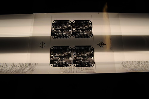
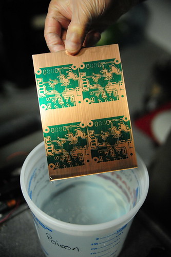
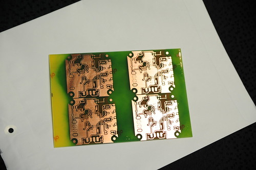
To fix this dilemma, my friend an I have decided to build our own stepper driver PCBs. TechZone will sell individual PCBs, but we decided that it would be interesting to try the new 3.0 driver and see how well it works. We have PCB making supplies, and are currently in the process of getting a couple more things. We're going to go ahead and try the UV method to put down the resist, so hopefully that will work out well.

I've asked around about people using the 3.0 drivers, but all I can find is a forum post saying they'll be available for purchase sometime around February.. Well, it's been quite awhile since then, and the design on the SourceForge hasn't changed in 5 months or so. I'm assuming there just hasn't been any more testing on it. We've got the components ordered up to build 3 of them, and the tools to do all the SMT work. Hopefully we'll be able to get a usable board out of this process. We will also document what we're doing here, cause it's a pretty exciting thing to make your own PCBs and build them!

Aside from that, the axises on the machine are all moving with the stepper controllers we have. The TechZone board did not come with a bootloader burned on the chip, but luckily we had a USBtinyISP that we used to burn one on there. After that and a quick load of the FiveD firmware, things are moving around. We'll do the same for the extruder controller soon and hopefully it'll be running the machine within a week or two! Then we can start tuning Skeinforge again. I can't wait.

(photos will be posted later today)