 | |
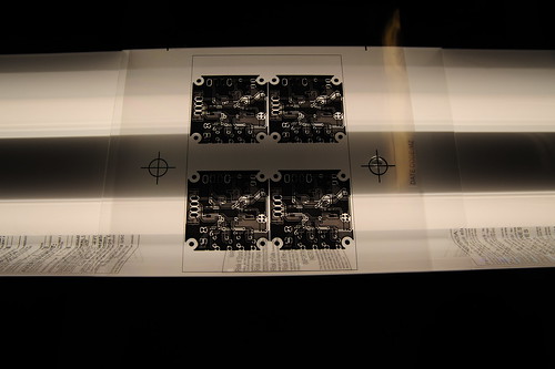
| Fluorescent lights upside-down with glass for registration |
The boards are a dark greenish color when you remove the protective sheet from them, the light blue is just a thick film that covers the board that needs to be removed. We pulled it off and set the board in the area we had decided on, and slid it between the glass and under the light. We then set the timer for 8 minutes and exposed each side for that amount of time.
 |
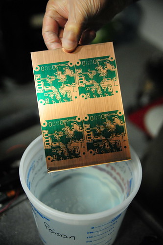
| Immediately after developing. Green is the resist. |
After exposing, you can barely see the pattern on the board. The dark green has changed to a dark yellow-green, so it's hard to really tell without a bright light, which you can't use yet. Next, you drop the board into a mix of 1 part developer to 10 parts water, and swish it around. Immediately the developer begins to remove the resist and you can see the circuit pattern.
After developing, we needed to actually etch the PCB. We mixed two parts Hydrogen Peroxide with one part Muratic Acid and used that to etch. This stuff fumes pretty good when you mix it, so I'd advise doing that bit outside or in a well-ventilated area. Careful breathing around it or you'll be coughing a lot. We dipped the PCB into the solution and began swishing back and forth by tipping the container. The solution begins to turn green quickly and you can see wisps of material coming off the board, but the process takes about 4 minutes before you see any clear progress. This usually starts around the edges where the copper begins to be completely etched away, revealing the fiberglass board beneath. The total time we had was about 6-7 minutes of gentle agitation and flipping the board every so often.
 |
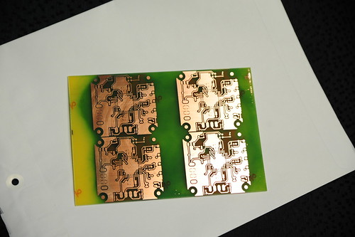
| Final product. Green is stains from removing the resist. |
After etching has completed, we rinsed and dried the board, then removed the resist with Acetone. It comes off pretty readily, but also seems to stain the fiberglass. Not a big issue. What's left is ready for drilling and soldering. I used a script in the EAGLE software called 'drill-aid', which takes the large holes normally printed for the vias and components and fills them in, leaving only a tiny 0.3mm hole in the center. This helps with drill centering, I'm told, so I went ahead and used it, and the tiny holes etched perfectly.
The finished product is really good. Although I still would like to get it on the stereoscope at work and take a look at it really up close, everything I can see went perfect. The process was so complete, that even a place where the toner had a few holes showed exactly the same on the board. (The toner is several years old, as is the printer, an HP LJ 2200D.) We're really excited about the possibilities of what we can make with just some simple work on the computer. I'm really interested to try my hand at laying out some boards myself!
Those who have been working with the Stepper Driver 3.2 will notice that the board there is a little messed up. I accidentally mirrored both sides, and this caused the board to be etched incorrectly. Now there's no way to actually make these boards work, so we're calling this our photoresist test board, and we're going to do another using better transparencies, a better printer with darker toner and higher resolution, more accurate registration marks, etc. Hopefully the next will turn out just as good, or hopefully even better than the first!
(There will be a video of the etching process posted tonight, I need to edit it up a little.)
No comments:
Post a Comment