Wednesday, July 14, 2010

Active Directory and BackupPC

This post is going to be slightly off-topic. Mainly because it's the best place for me to put this information.

When I spend a couple days getting a particular setup to work properly, I feel I should post about it as many others have to help someone out who's in the same boat. So, without further ado, here's how I set up BackupPC to work on my corporate network using ADS authentication.

For this setup, I'm using Ubuntu Lucid Lynx 10.04 Server 64-bit with the latest packages as of 7-14-10. This includes BackupPC v3.1.0.

My setup is this: I have the Ubuntu box (backuppc-srv) running as a VM on a local server. For all intents and purposes, this should not change any configuration as it's bridged networking. We have a set of Windows XP machines that need to be backed up. All machines including the server are joined to the corporate domain (Contoso) and have a FQDN of (contoso.test.com) I have a domain account that has the ability to create computer objects and join machines to the domain, however, I do not have console access to the domain controller. This will come into play later when we create the keytab.

The Ubuntu help sites have started recommending using Likewise to join the domain. While this is easy to do with a desktop, while trying to get Kerberos working, I had nothing but problems with it, and eventually removed it and decided to go about it with straight Samba. It's actually not that hard, and just requires a little work.

We first need to set up the machine to join the domain. I used this excellent blog post here which I will use several commands from to illustrate the process.

As the linked article mentions, it is very important to have a good working DNS setup on the domain. ADS relies heavily on it for authentication and will not work without being able to do forward and reverse lookups. Also, make sure that your machine has good time synchronization. Chances are, if you have a Primary Domain Controller (PDC) it will also be running as a time server. You should be able to use ntpd or ntpdate to synchronize time, which is also very important to Kerberos, as it is normally configured with a narrow clock skew. More than a few seconds difference and you can experience some issues.

To start, this command can be used to install the requisite packages to run Kerberos and Apache authentication:

backuppc-srv:~$sudo apt-get install apache2-mpm-prefork libapache2-mod-auth-kerb krb5-config krb5-clients krb5-user samba-client openntpd

Now that we have the packages installed, we need to setup Kerberos to authenticate to the proper domain.

Edit the /etc/krb5.conf file with your favorite text editor and start looking around. By default there are a few comments that may or may not be helpful. Here's how mine is:

[libdefaults]

# The following krb5.conf variables are only for MIT Kerberos.
        krb4_config = /etc/krb.conf
        krb4_realms = /etc/krb.realms
        kdc_timesync = 1
        ccache_type = 4
        forwardable = true
        proxiable = true
        default_realm = CONTOSO.TEST.COM

Under the next heading you should set up your PDCs.

[realms]
    CONTOSO.TEST.COM = {
        kdc = pdc.contoso.test.com
        master_kdc = pdc.contoso.test.com
        admin_server = pdc.contoso.test.com
        default_domain = contoso.test.com
    }

Now that those are set up, put in the last couple bits here to make things work right:

[domain_realm]
.test.com = TEST.COM
.contoso.test.com = CONTOSO.TEST.COM

Now those are out of the way, we can test the Kerberos setup by using kinit. domainuser is the name of some user account who is in the domain and enabled, i.e., it works on other machines.

backuppc-srv$ kinit domainuser
Password for domainuser@CONTOSO.TEST.COM:

Once you've done this, you can check to see if it issued you a ticket by using klist.

backuppc-srv$ klist
Ticket Cache: FILE:/tmp/krb5cc_0
Default principal: domainuser@CONTOSO.TEST.COM

Valid starting      Expires            Service Principal
07/14/10 12:00:15   07/14/10 00:00:25  krbtgt/CONTOSO.TEST.COM@CONTOSO.TEST.COM

Now we see that the account has been issued a ticket. You can then release the ticket with kdestroy:

backuppc-srv$ kdestroy 

Now we can setup Samba. Edit the file /etc/samba/smb.conf. These lines will be scattered throughout the file, if they're not there, just put them in the general section.

netbios name = backuppc-srv
realm = CONTOSO.TEST.COM
security = ADS
encrypt passwords = yes
password server = pdc.contoso.test.com
workgroup = CONTOSO

You should also add the keytab settings for completeness:

keytab method = dedicated keytab
dedicated keytab file = /etc/krb5.keytab

Now we can join the computer to the domain. Domainadmin is a user on the domain who has privileges to join a computer to the domain.

backuppc-srv$ sudo net ads join -U domainadmin

It will do several things which will eventually end up joining the computer to the domain.


Now you should ensure your /etc/hosts file is setup correctly. It will have your computer name (backuppc-srv) linked to your localhost as such:

127.0.0.1 localhost
127.0.0.1 backuppc-srv.contoso.test.com backuppc-srv

You need to add another line to this with your server's IP address. 192.168.1.123 is the IP address of backuppc-srv

192.168.1.123 backuppc-srv.contoso.test.com backuppc-srv

When this is all completed, we can now get a keytab so that Apache can use it to authenticate against the server. As the linked article mentions, a lot of the tutorials on the web mention using ktpass on the windows machine, but you don't always have access to that, or a secure method of transporting the resultant keytab into the linux box. Luckily you can just get Samba to get one right off the PDC.

backuppc-srv$ sudo net ads keytab add HTTP -U domainadmin

This will get a keytab, and put it into the default file specified in the krb5.conf file, which is /etc/krb5.keytab in this example.

You can now verify that the keytab was successfully retrieved by using klist.

ktutil: (the last command is a lowercase L)
backuppc-srv$ sudo ktutil
ktutil: rkt /etc/krb5.keytab
ktutil: l


This method is much easier than typing all that stuff and was just recently brought to my attention:
 
backuppc-srv$ sudo klist -k /etc/krb5.keytab

slot KVNO Principal
---- ---- ---------------------------------------------------------------------
   1   13 HTTP/backuppc-srv.contoso.test.com@CONTOSO.TEST.COM
   2   13 HTTP/backuppc-srv.contoso.test.com@CONTOSO.TEST.COM
   3   13 HTTP/backuppc-srv.contoso.test.com@CONTOSO.TEST.COM
   4   13            HTTP/BACKUPPC-SRV@CONTOSO.TEST.COM
   5   13            HTTP/BACKUPPC-SRV@CONTOSO.TEST.COM
   6   13            HTTP/BACKUPPC-SRV@CONTOSO.TEST.COM

This shows that there are the proper entries in the keytab.

You need to then give permission to Apache to read the file.

backuppc-srv$ sudo chmod 740 /etc/krb5.keytab
backuppc-srv$ sudo chgrp www-data /etc/krb5.keytab

Now it's time to get apache working. You can use the command a2enmod auth_kerb to ensure that mod_auth_kerb has been properly enabled.

Now we need to edit the backuppc Apache configuration to tell Apache how to authenticate users.
The file to edit is located in /etc/apache2/conf.d/backuppc.conf
This is how my file has been setup. I have commented out the four lines at the bottom there, leaving the require valid-user line in place. I added the six lines at the top.
 
AuthType Kerberos
AuthName "Kerberos Login"
KrbAuthRealms CONTOSO.TEST.COM
Krb5Keytab /etc/krb5.keytab
KrbMethodNegotiate On
KrbMethodK5Passwd On

# AuthGroupFile /etc/backuppc/htgroup
# AuthUserFile /etc/backuppc/htpasswd
# AuthType basic
# AuthName "BackupPC admin"
require valid-user


Now that apache is setup, make sure you restart it (sudo /etc/init.d/apache2 restart), or perhaps better, reboot at this point, just to make sure the domain join is working properly. After it restarts, try to access the backuppc web interface. If you are getting the Kerberos login prompt, login with your domainuser name. No domain prefix is required as it's set to logon to a specific domain and Kerberos on linux cannot handle cross-domain logons.

If you are having errors, it's best to tail -f /var/log/apache2/error.log and set the debug level to debug in the /etc/apache2/apache2.conf file to display errors while attempting to login.

If you get a failed to verify krb5 credentials: Server not found in Kerberos database error, that's usually due to DNS issues, double-check your hosts file that you have the right IP addresses and names listed.

Client not found in Kerberos database means just that, it can't find that username. Make sure it's valid on the domain. I found that trying to logon to backuppc using a local linux user doesn't seem to work afterward, maybe I'm not setting something up right.

Wrong principal in request usually has to do with the keytab file. Check to make sure it has the HTTP sections, and if it does, just delete and recreate it with the command above used to initially make the file. Remember to change the permissions back! This has been the fix for the authentication randomly dropping occasionally, for me.

Once you've got yourself logging on via Kerberos, edit the backuppc /etc/backuppc/config.pl file with the proper user settings. I found that i needed to add the domain to make it recognize the user.. i.e. assign a computer with 'user' set to domainuser@CONTOSO.TEST.COM and that should work when they authenticate. You can also add a user into the CGI admin group in the same file, in the same way to allow that user to have admin access.

You will need to make a modification to the samba command that BackupPC uses if you back up with a local user account that's on the computer and not on the domain. On the Xfer tab of the BackupPC config, just before the -U $user, add -W $host. This will tell Samba that the username you're specifying is for the 'local host' domain, i.e., don't try to authenticate to the active directory, only authenticate locally to the computer. In my case, the local backup user accounts are not valid domain users, so this change needs to be made.

I'll update this when I figure out how to get Single Sign-On working on this through IE6. Right now i'm getting a gss_accept_sec_context() failed: An unsupported mechanism was requested (Unknown error).

Tuesday, June 15, 2010

Stepper Driver is live!

I brought the completed boards that my friend had drilled and cut out to work, and started the process of populating the board with all the fun components that make it work.

I formulated a strategy, which was to install all the tiny vias, then use the large Chipmaster hot-air machine to flow the large chip and the big current sense resistors on, then solder on all the other smaller SMT components with a hot air pencil, then do the large through-hole components. I chose this mainly because if I were to hot air the large chip last, the air temp would cause many of the plastic pieces on the big components to melt, or blow some of the smaller components off the board.

First power up!
Overall, the technique worked well. I produced a working board with only one small short, which I located and fixed. I then took the board up to FamiLAB, where we tried to hook it up and get it working. The blue light came on, which is power, so we were quite happy there. Then, after fiddling around and finding we had a bad cable, we got it to start stepping!

We got RepRap host up and running and started jogging the stepper around on it, which worked great! We enabled and disabled microstepping, which seemed to also work quite well. All the LEDs and such were running properly, and the chip barely got warm. All good signs. We even took a short video of the first movement here:


Now tomorrow I need to start work on the second one, and I'll have enough drivers to run all the motors. Then it's on to finishing up the electronics...

Wednesday, June 9, 2010

We have PCB!

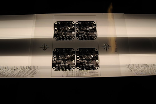
So up at FamiLAB last night, we spent some time getting the PCB setup going.. I got some containers to do the PCB etching and developing in, and a few other bits and pieces needed. I started the PCB thing by printing the masks onto paper and holding them to our fluorescent light source to line things up and see how well they would fit.
Fluorescent lights upside-down with glass for registration
Once I had the designs set up properly and it looked good, I printed them out on the transparencies we got. Then we lined them up, used a little spray adhesive on the far corners to hold registration, and opened the board.

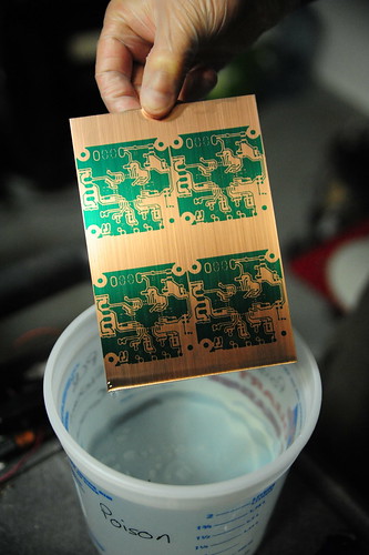
The boards are a dark greenish color when you remove the protective sheet from them, the light blue is just a thick film that covers the board that needs to be removed. We pulled it off and set the board in the area we had decided on, and slid it between the glass and under the light. We then set the timer for 8 minutes and exposed each side for that amount of time.
Immediately after developing. Green is the resist.

After exposing, you can barely see the pattern on the board. The dark green has changed to a dark yellow-green, so it's hard to really tell without a bright light, which you can't use yet. Next, you drop the board into a mix of 1 part developer to 10 parts water, and swish it around. Immediately the developer begins to remove the resist and you can see the circuit pattern.


After developing, we needed to actually etch the PCB. We mixed two parts Hydrogen Peroxide with one part Muratic Acid and used that to etch. This stuff fumes pretty good when you mix it, so I'd advise doing that bit outside or in a well-ventilated area. Careful breathing around it or you'll be coughing a lot. We dipped the PCB into the solution and began swishing back and forth by tipping the container. The solution begins to turn green quickly and you can see wisps of material coming off the board, but the process takes about 4 minutes before you see any clear progress. This usually starts around the edges where the copper begins to be completely etched away, revealing the fiberglass board beneath. The total time we had was about 6-7 minutes of gentle agitation and flipping the board every so often.
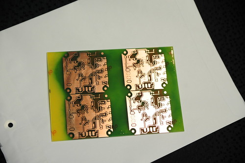
Final product. Green is stains from removing the resist.


After etching has completed, we rinsed and dried the board, then removed the resist with Acetone. It comes off pretty readily, but also seems to stain the fiberglass. Not a big issue. What's left is ready for drilling and soldering. I used a script in the EAGLE software called 'drill-aid', which takes the large holes normally printed for the vias and components and fills them in, leaving only a tiny 0.3mm hole in the center. This helps with drill centering, I'm told, so I went ahead and used it, and the tiny holes etched perfectly.

The finished product is really good. Although I still would like to get it on the stereoscope at work and take a look at it really up close, everything I can see went perfect. The process was so complete, that even a place where the toner had a few holes showed exactly the same on the board. (The toner is several years old, as is the printer, an HP LJ 2200D.) We're really excited about the possibilities of what we can make with just some simple work on the computer. I'm really interested to try my hand at laying out some boards myself!

Those who have been working with the Stepper Driver 3.2 will notice that the board there is a little messed up. I accidentally mirrored both sides, and this caused the board to be etched incorrectly. Now there's no way to actually make these boards work, so we're calling this our photoresist test board, and we're going to do another using better transparencies, a better printer with darker toner and higher resolution, more accurate registration marks, etc. Hopefully the next will turn out just as good, or hopefully even better than the first!

(There will be a video of the etching process posted tonight, I need to edit it up a little.)

Tuesday, June 8, 2010

Almost there...

Well, we're still working on finishing up the bits and pieces of the Mendel. Mainly, we need to get the PCBs done for the stepper controllers. My partner in crime ordered some stepper motors and those should be coming in today or tomorrow, and we'll be using those with the stepper controllers to get this thing running.

In my previous post I was talking about the Stepper Driver 3.0 that we were going to be building. Well, I got a short email dialogue with Zach Hoeken and he informed me that the modifications that Nophead suggested were made on the newer revision of the board, which he directed me to. (the XLS file is out of date, schematics are up to date)
So, the only problem is that I ordered all 1206 parts, when the new revision changes up a lot of components for 0805 parts (SMT part sizes). This causes an issue cause the parts I ordered are too large now to fit on the revised board's pads. So, I need to order all new parts, which I did yesterday. Hopefully the LEDs will be nice.. I got a good variety.. Deep Red, True Green, and Hyper Blue. RGB are my favorite colors to have on things.

We got the PCB boards and developer in, and we're going to make some Cupric Chloride to etch the boards. It's much safer than the Ferric Chloride, and better for the environment too. I spent last night working a little in Eagle. The light version won't let you panelize the board because it's too big, so I exported each side of the board as a PDF and then imported it into Inkscape. From there, I created an outline the same size as our board to help me in positioning the sides, then used align tools to create top/bottom layers. Now I can mirror the top layer and print them onto transparencies. We're building a UV light source with a lot of LEDs to see if that will expose better than fluorescent lights. It seems to be pretty sensitive, the package says to expose for 60-90 seconds under "exposure unit" which we're assuming is a UV source. or 6-10 minutes under a normal fluorescent lamp.

I got around to redoing the H bridges on the extruder controller, because I had hooked it up backwards to 12v at one point and blew the H bridges. So now I have a new set of H bridges on the board, so we should be good to go. However, I'm still going to be using the Stepper Driver 3.2 on the board. I may use the 3.2 boards I'm making for the X and Y axises, and the normal ones for the Z and extruder, as they require less precision. The 3.2 boards are tunable via 4 potentiometers and also have selectable microstepping. That will be an interesting feature to experiment with.

I'll try to get some photos or video of the etching process, as I think it would be a cool thing to watch!

Tuesday, June 1, 2010

Lots of progress!

Well, I apologize for the lack of updates, but we're in a pausing point here, so I will post a bunch of stuff that documents our progress since the last post.

When we last left our hero, he was having issues getting the MakerBot to work properly with the new FiveD firmware. Since then, we've managed to figure out what's up, remove those offending M codes from the file (M101, M103) and get printing again.

I've gotten the Wade's extruder all tuned up in Skeinforge, and it's doing an awesome job printing parts. We've even gone back and reprinted parts during our assembly that were done on the old Plastruder, and they've come out with much better tolerances on the new extruder. I've gone ahead and printed out another copy of it to use on the Mendel, so we will see how it works on there!

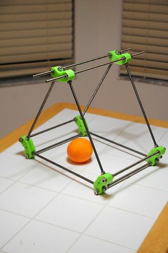
The Mendel. Yes, we started construction as we neared just a few parts left, and have gotten it pretty much completely built! There are a few little quirks here and there, like if you're using Josh Updyke's milled plastic frame vertexes, you should add another 1/2 to 3/4" to your x-plane rods. We added more washers to the Z belt bearings to space them out further from the plastic. We created our own M3 set screws with a Dremel, and hopefully have a good hobbed bolt for using on the new extruder!
I've almost finished up the HeatCore for the Mendel, which we'll be using temporarily while I experiment with the cartridge heater and copper block I'm building.

(When I say "we" I mean myself and another friend at our hackerspace, who is also building a Mendel.)

While I originally planned on documenting the entire build by photo, we had forgotten to do this and decided that when we build the second one, we will try our best to document the build process.

Other than that, the build went fairly smoothly. Belts are attached, frame is squared and tightened down, and we got some of the electronics mounted up on it. That's our current holdup. I used one of the stepper drivers in the MakerBot to drive the stepper for the extruder, and the TechZone kit only comes with three. So currently we're at two stepper drivers, and one half-broken extruder controller (I hooked the 12v up backwards and fried the H bridges.. but hopefully we won't need those).
To fix this dilemma, my friend an I have decided to build our own stepper driver PCBs. TechZone will sell individual PCBs, but we decided that it would be interesting to try the new 3.0 driver and see how well it works. We have PCB making supplies, and are currently in the process of getting a couple more things. We're going to go ahead and try the UV method to put down the resist, so hopefully that will work out well.

I've asked around about people using the 3.0 drivers, but all I can find is a forum post saying they'll be available for purchase sometime around February.. Well, it's been quite awhile since then, and the design on the SourceForge hasn't changed in 5 months or so. I'm assuming there just hasn't been any more testing on it. We've got the components ordered up to build 3 of them, and the tools to do all the SMT work. Hopefully we'll be able to get a usable board out of this process. We will also document what we're doing here, cause it's a pretty exciting thing to make your own PCBs and build them!

Aside from that, the axises on the machine are all moving with the stepper controllers we have. The TechZone board did not come with a bootloader burned on the chip, but luckily we had a USBtinyISP that we used to burn one on there. After that and a quick load of the FiveD firmware, things are moving around. We'll do the same for the extruder controller soon and hopefully it'll be running the machine within a week or two! Then we can start tuning Skeinforge again. I can't wait.

(photos will be posted later today)

Saturday, May 1, 2010

FiveD MakerBot Mishaps

Well, not to start out unhappy, but I've been working a lot on trying to get this thing to work right. It's not easy, let me tell you. I've had a few successes, but it seems I've run into every problem possible while doing this.

Now I've got my machine set up with the endstops and motor directions (by moving endstops and reversing motor cables) so that from the front, it plots in the same direction as all the software we use shows us things. i.e., origin is closest to viewer, left. (Bottom-left). This helps not build parts backwards, and makes visualizing the platform and x/y movements a bit easier.

The geared extruder is hooked up and running well. Haven't had many issues so far with the extruder itself; as a matter of fact it's gone quite well. The big part has been getting the table and software to work well.

A lot of the issues I had tonight dealt with Skeinforge. I'm using the latest version as of the time of this writing (2010-04-26). The RepRap host software (once I figured out some decent settings, which I'll post tomorrow) works good enough to get out a demo print. It's not perfect, but it will build an object.. roughly.

The objective here is to use Skeinforge's Gcode creation to build objects, since it's much more developed than the other. We still use RepRap Host software to send the gcode to the printer, but Skeinforge is doing the creation. I'd like to try/use RepSnapper soon, but it has issues with the 3d on this laptop.. seems the Intel drivers on here aren't really up to par for 3d stuff. We'll have to wait until they fix that. It doesn't run all that hot in the VM on here.

Had an issue earlier with the Z axis not working correctly. Turns out, Skeinforge's Z feedrate needs to be set quite low.. mine's set to 1.5mm/sec. Set anywhere higher and it freaks out a lot..

My main problem was that I had issues with it doing odd things.. I tried printing calibration blocks, but they definitely were not correct, and when I tried printing a 20mm solid block, I knew we had an issue.. Here are the photos:

Three calibration blocks. That triangle is there instead of the second shell on the other two sides..

20mm solid calibration block. This one's outline was extruded as huge blobs in the corners for some reason.
With these two, they have very different and odd issues. Mainly, the extrusions are not working properly. Visualizing the Gcode in RepSnapper shows that the code is proper.. somewhere between the code and the machine, something's not getting interpreted correctly.

So I did some investigating.. I loaded up the same object in Skeinforge and RepRap Host, and generated gcode files, and tested printing them. The RepRap Host file printed properly, and the Skeinforge file didn't. I then opened up the Gcode files side by side and tried looking for differences between the two.

In the Skeinforge file, whenever the extruder starts and stops, the file issues M101 and M103 codes. These are extruder start/stop commands, usually used with DC gearmotors. They tell the controller "start extruding, stop extruding" all at the preset speed. However, with stepper motor extruder drives, the extruder is treated as another axis, and therefore does not need on/off commands, as the stepper routines and controller take care of positioning the stepper appropriately.

One would think that these commands would be ignored, then. However, the RepRap Host file did not contain these codes. When I removed them from the Skeinforge file and reprinted (using the RepRap Host software), the file printed properly. I don't know what is causing this, the firmware or the host software, but one of the two just can't seem to handle those codes when it's using a stepper extruder. I used a simple find/replace command to delete them, and the files Skeinforge produces are working now.

Wednesday, April 28, 2010

Success!

Finally some good news!

Was up at FamiLAB last night working on the MakerBot. Got pretty much everything working right, defined some temperature sensor stuff and configured the extruder controller's firmware and uploaded it.
Did some simple tests with temperature and the HeatCore, found it's working well! The temps with the thermocouple are rock solid, and the PID on the extruder does a great job. I decided to run some test extrusions just to squirt out some filament, and they're great! Coming out nice and smoothly, if a bit slow. Temps seem good, it's not burning the filament, and I went through a few start and stop, heat/cool cycles to make sure we weren't having any issues with the nozzle. Everything looks good so far!

I decided to push my luck really hard and get it to try a simple build, but the X axis just kept driving itself into the wall, and the RepRap host software seems to be buggy at best when it comes to working with Gcode files.. I need to play around with it more and figure out what it's trying to do.

I've taken the stock MakerBot electronics and used them as-is, no mods to the boards or anything. All I've done is take an extra Stepper Motor Controller from my Mendel electronics kit and hook it's step/direction up to the I2C connector on the motherboard with a 3 pin header. All that's needed for the stepper controller to operate is step, direction, enable, and ground. Enable is tied to ground so that the board is always on. Step/Dir will depend on the connector you are using coming from the stepper controller, but I'll post a small diagram a bit later. This is hooked into the extruder's stepper motor, so the motherboard actually controls the extrusion steps instead of sending that info over RS485 as MakerBot does. The extruder controller is now only used to control temperatures of the nozzle, bed, and a fan if used.

The thermocouple is attached using a Thermocouple Sensor board from MakerBot. I'm using the AD595C for higher precision, and have the thermocouple taped so that the tip rests in the thread near the end of the nozzle, not touching the HeatCore. The sensor board has three wires; Vcc, GND, and Sig. I hooked these up using a small 3-position connector that came with my Mendel electronics kit, and plugged them into the MakerBot extruder controller on A7.
The FiveD firmware has support for Thermistors, AD595 Thermocouples, and MAX6675 Thermocouples. All that's needed to do is edit configuration.h to uncomment the proper thermocouple #define line, make sure the others (such as USE_THERMISTOR)  are commented, and change the #define TEMP_PIN to 7. This will set up the unit to read the AD595 from analog pin 7, and it will work just as normal. Need to be careful not to short the thermocouple wires as they're bare, and they will cause spurious readings if they're shorted. A single wrap of Kapton around the leads just behind the welded tip should be sufficient.

As far as further configuration of the FiveD software for MakerBot, I'm still trying to get it to a working fashion.. The axis can be easily calibrated using the standard method prescribed by RepRap. I used the 100mm to start though, so it would take less time to calibrate. All movements are accurate right now. I'm working on getting the home offsets correct, and hopefully being able to use the build limits as well so it doesn't try to build off the bed.

I will post more photos and perhaps a video tonight when I head back up to the lab to work more on this. Until then, here are a couple I took with my phone last night.


Monday, April 26, 2010

Finally getting somewhere..

Well as you may know from reading previous posts, the MakerBot at FamiLAB decided to puke up and break it's extruder somewhat. I tried to fix it, it kept having issues driving the DC gearmotor, and it was basically nonstop unhappiness. So, I decided, with all these Mendel parts hanging around, why not incorporate some of them into the MakerBot to get it at least up and running so it can print us a Mendel?

So here I begin...

Using the official MakerBot firmware with a geared stpper extruder is just way too much work and isn't really going to cut it. So, I decided to try and get RepRap's FiveD firmware up and running on the unit. It'll be good for a couple reasons.. One, I can do a few more things than I could with MakerBot, there's faster releases and better support for mods, since it was built to run a stepper extruder and has support for thermocouples out of the box. Two, I get more face time with it to really understand how that firmware and the apps work, so that when I finally get the Mendel built I'll already be pretty experienced in how to operate it and get things going.

So, I started off on that last night, getting the FiveD firmware set up with all the right pins, compiled, and uploaded to the MakerBot. I wired up a spare stepper motor controller to the extruder stepper and the I2C pins on the motherboard. I believe the H bridges in the extruder are kind of shot, so I'm doing this to get it running for now. I'm going to be making up a little mounting plate very shortly to get the Wade's geared extruder mounted up on the MakerBot Z platform. I may just clamp it to one side for now, just to test and get things moving, but I do want to get it set up properly with a bracket.

I calibrated all the axis and they seem to be moving proportionately now. Since the machine wasn't using endstops before, I had to set them up, test them and build some endstop triggers, which I made out of beer cans that happened to be laying around at FamiLAB. They seem to be working well, but I need a better way of attaching them as electrical tape just isn't cutting it. Other than that, auto-homing works properly now, all axis move, and are accurate.

The next step for hopefully tonight will be to get the extruder mounted up and start testing it.. I'm not so sure the speed settings are correct right now, but that's part of testing. I have the 0.5mm refsynderb nozzle in there and it's pretty much ready to go, just need to screw on the MakerGear HeatCore, attach my thermocouple and test that, and we should be ready to roll. I need to figure out how to get the heated build platform operational as well...

I'll be posting all this on the MakerBot wiki, as converting a MakerBot over to a geared extruder and FiveD has been an interesting task. I've been gathering some notes on the topic, and I'll be posting some pictures as well.

Thursday, April 22, 2010

Well I tried my hand at modifying some firmware and such, was a bit of a bust but here it goes:

Changed the v1.8 Heated Bed firmware to support the stepper extruder and also modified some code to use a thermocouple instead of a thermistor for the extruder temp sensing. Went up to FamiLAB and tried it out.. the thermocouple worked fine, but the stepper motor would not mobe. I'm not sure what the issue was.

The unfortunate thing is that there's no mention of how to wire up a Lin Engineering stepper to an extruder controller. They use Red/Blue/Green/Black wires, and I ohmed out the stepper looking for the two coils, which I found, and hooked up to the 1A/1B/2A/2B posts on the extruder controller. Tried to enable it and the H bridges got really hot, but no motor movement. The bridges stopped outputting power after that.

Looking in the Makerbot Operators group, someone mentioned that having a stepper connected that was less than 6 ohms might cause the H bridges to burn up; the Lin Engineering ones are about 1.8 ohm. However, they're also recommended on the RepRap website as steppers to use on the extruder controller. I'm a bit confused here, how are they normally used? There's a distinct lack of documentation as to what the resistance should be across the stepper terminals, so I'm of the assumption the H bridges were bad anyway and I didn't screw up there.

However, I did manage to screw up afterwards. Some folks in the Reprap channel on freenode were trying to help me troubleshoot the problem, when I managed to find out that the extruder controller has no reverse current protection in it. Hooked the 12v up backwards and blew the H bridges on my new board. Well damn.

So I'm ordering 6 new H bridges from Digi-Key, hopefully i can just replace them and that'll fix the boards, and perhaps try again to see if it was the bridges or if the stepper is the problem.

If anyone has some insight into this, it would be much appreciated. Been an ordeal just trying to get this working..

Monday, April 19, 2010

Slowly moving forward

Well, I haven't posted recently because I haven't spent much time actually building this thing, but here's a post to sum up what's been going on as of late. It's a bit long, but a lot is talked about here! MakerBots, Extruders, Thermocouples and firmware!

Friday, March 26, 2010

Electronics

Well, over the last couple days I've gotten a few pieces in.

- The geared extruder based on Wade's design
- Full electronics set for the machine
- Copper bar and cartridge heater for the barrel

So here's a few photos:

First, the extruder. This is how I assembled it, I believe this to be correct based on the illustrations I've seen

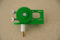
Extruder with nozzle


Saturday, March 20, 2010

Thermocouple

Just wanted to throw a little bit up here about the parts that came in today..

I received my order in from SparkFun electronics earlier today, and since it had the requisite bits needed to build the thermocouple amps, I built that.

Thermocouple Amp

Thursday, March 18, 2010

Parts are coming...

Well, after I got the heater thing posted, I had more parts awaiting me when I arrived home from work.

I got things from MakerBot and DigiKey, so I took pictures of everything.


Stuff!

Heaters..

Well I usually head out to the RepRap forums daily and check out what's new on the site, get a feel for what people are doing and if there's any good deals like the geared extruder from earlier in the week.

I started reading up about extrusion heaters on a thread in the RepRap forums. It referenced Nophead's interesting heater design, utilizing an aluminum block with a nozzle machined into it. Unfortunately, I don't really have the equipment to machine myself some nice heaters, so I'm basically making due with what I do have.

So, I've been thinking a bit more about this, and I've come up with a couple ideas to try:


Extruder NozzleMainly, since I got heater barrel/nozzles already from refsnyderb, I'm looking into ways to use this nozzle instead of making another. The big thing that seems kind of fragile about the nozzle/heater on the normal RepRap is the fact that nichrome wire is used, being wrapped around the barrel. This seems to have some issues, mostly the element getting burned out which requires a complicated rebuild of the nozzle.


Tuesday, March 16, 2010

Power

I didn't mention in my last post, but I ordered a 12VDC 8.5A power supply from MPJA.
Power Supply
I overrated it because I like to do that, and since I might be moving up to a larger stepper or controlling something else with it later on.
Got the PSU in today, since MPJA is in Florida.

I also took a gander at the reprap boards and found that RustySpoon is selling his geared extruder utilizing an NEMA 17 motor and a pair of reprapped gears with a hobbed shoulder bolt and spring-loaded idler bearing. Looking over the wiki article, it shows some pretty amazing results with the amount of pressure it's able to exert on the filament, showing over 15kg of pull before the stepper started running in reverse.. Looking at the stepper that's being used, it's approx. 69oz/in, so the slightly larger 75oz/in might have even a bit more pull..
So, I ordered one of those as well, and I'll probably use that as the extruder instead of building the one that comes with the kit.

All these parts that I'm adding in are starting to decrease the amount of RP parts I'm going to need to finally get this thing put together. Hopefully things will move quicker now that most of the bits and pieces are on the way or already here.

Sunday, March 14, 2010

It's on the way..

Well, I found I had some more money available for the RepRap, so this weekend I decided to get more of the parts necessary to make the machine. I've now got the following on the way:

1 NEMA 17 Bipolar Stepper for the extruder
3 NEMA 17 Bipolar Steppers for the axes
Electronics Kit (all the electronics/boards assembled)
2 Thermocouple sensor PCBs
      - Also bought the more accurate AD595C variant of the AD595 (a little pricier)
      - With thermocouples and terminals from SparkFun
10ft of Nichrome Wire
1lb of colored ABS filament

Also got a nice 1/4W carbon film resistor kit from SparkFun as I've been wanting one for awhile. Always nice to have resistors handy (even if they aren't precision)


So all that stuff should be coming in this week here, and I'm also looking for a way to get at some of the RP parts. Might be helping some people from FamiLAB with getting their MakerBot tuned up. Getting some time with the software would also be helpful so I can figure out how it all works.

Thursday, March 11, 2010

A frame!

Well, I spent all night working on the RepRap (and making a banana cake. I loooove cake) and the outcome is this:

Finally, a frame!


Moving along!

Parts
(Just came out of the box!)

Okay! Making a bit more progress with the build! Over the past couple days I've gotten in all the belts and metal parts from McMaster-Carr, the smooth rod from SmallParts, and the bearings from VXB.


Monday, February 15, 2010

Building steam

Although my posts are slower than before, the project is still moving.

I got in some more nice parts the other day in the form of a set of frame vertexes from Josh on the RepRap forums. They're milled from plastic stock, so they're pretty solid and feel quite nice. They were easier to make that way due to their simplicity, and they came out pretty good.


Looking for hardware now. I'm pricing out parts and updating my spreadsheet with the prices and quantities that I'll need. The RepRap build instructions are woefully inadequate, they're very partially completed. Some of them trail off and others are very basic.
An example of this is while I'm trying to make sure I get the right leadscrew, I look to see how the leadscrew attaches to the X bed to see what type of nut they use. Well, there's not much there in the instructions.. and it seems a lot of the illustrations are incorrect and need to be fixed..

So I'll go ahead and assume for the time being it's just a normal nut and get some of those like it calls out. I'm also getting the belts and other hardware together so that i'll have at least the base set of goods, while I'm trying to find other places to get the RP parts from.

For now, I'm waiting on a little more play money to have so I can do this. My phone's starting to frustrate me to the point of wanting to chuck it out a window because it's so slow; I'll most likely be getting a Nexus One come Thursday.
The project moves on!

Monday, February 8, 2010

Taking time

Well since I'm back to more work at work, there's mainly just time at home now devoted to working on the RepRap. I've been looking for sources for the electronics.. I know that shouldn't be my top priority, but I've still been looking.

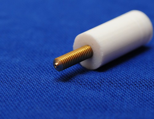
Got the extruder nozzle in today, took a couple pictures of it since there weren't any good ones at the time.

Extruder Nozzle

Since MakerBot has stopped carrying the v2.3 of the stepper motor controllers in favor of most likely moving to the v3.0 soon, I might be looking for an alternative stepper controller if I'm not able to procure some from the one lead I mentioned earlier.

The controller that's been mentioned and that I'm looking at is this one: A4983 Stepper Motor Driver Carrier with Voltage Regulators
It's been proven to work by some of the big names on the forums, so I think I could get it to work as well.

The next bit I'm going to start working on is the hardware bits and pieces. I need to locate somewhere like Fastenal that has a lot of the nuts/bolts/screws/washers/etc that I'm going to need for this thing. Getting all of those will help position me better for when the other goods come.

I've also been looking at some software casually, and while I haven't played with any of it yet, the stuff that's in use looks pretty darn interesting. I'm also looking into perhaps designing my own extruder.. I've got this idea for a gear reduction without using worm drive, so potentially less play in the gearing. My main thing is how to grip the plastic reliably, but i've been thinking up some ideas there as well. The whole extruder also needs to have parts bought for it, like the nichrome wire and motors I'm going to use.

I'll keep pounding away on this.

Thursday, February 4, 2010

Well so far I've started getting some parts orders going. I've been working on my spreadsheet for parts and been talking with a couple people from the forums..

So far I've listed all the parts needed for the frame and such that are RP-created.. Some of these I might be able to make myself, but others I'll have to source from someone with a RepRap. I do imagine this to be a bit slow, though I've already got a nozzle and set of vertexes on the way, and I may even have a set of stepper motors and stepper controllers coming soon as well!

I'll continue on with my spreadsheet and keep updating it with locations and people who I'm getting parts from, as well as post here with some notes on why I'm doing certain things.

The intro

The RepRap is an additive Rapid Prototyping machine built from simple parts and electronics, and is designed to be (mostly) self-replicating in that it will be able to create many of the parts required to build a copy of itself.

Here is a photo of one (this is not mine, it's copied from the RepRap Wiki)


The basic philosophy of RepRap is that it will be something that's easy to build, can be created with parts that are relatively easy to acquire, and can be had for much less than commercial solutions, which usually start out around $15,000.

So to begin, I will be making the Mendel version, which is the second (real) version of the unit. Darwin was the first, and used a cube-like structure, while the newer Mendel version uses a triangular prism shape. It also trades four lead screws to control the bed for two, making things simpler and giving the motors less to drive. Power consumption is a large factor in design decisions, as it seems most people are trying to keep the current draw low. This may be to enhance portable possibilities, such as running it off of a battery or solar panel. It would be pretty neat to be able to just set a panel facing the sun and hit a button, and let the unit start to work on a part, if the power drops too low it will pause and wait until it has enough to continue.. and eventually you'll get a fabricated piece! Perhaps that'll be my contribution, who knows!

Either way, I need to start getting the parts together. The RepRap Parts Lister seems to be somewhat out of date, so I will be using a Google Spreadsheet to list all my parts, locations, costs, and amounts, which should help anyone building a Mendel with finding the right items while being sure they'll work with the new version. It will also allow me to share it in realtime, which should help keep things up to date on this blog.

Here's the link: RepRap Parts BOM

I will most likely post this up somewhere on the RepRap forums so that people there can help see how wrong I'm doing things and hopefully steer me towards the right direction, but for now, I'm on my own.

The Project

Well this Blog was started as a bit of an attempt to publicize my life a little more as a lot of people do, but I've decided to make use of it here.

My project is to build a RepRap machine, and thoroughly document every step of the process, from finding parts to purchasing them, assembly, tweaking, software, every last bit that I can.

I have a D700 SLR camera and a good background in electronics and have played with Arduino and BASIC Stamp microcontrollers. I've assisted a friend in building a CNC table which (while not completed yet) has given me some insights into how some of these things work.

I'm hoping to get some knowledge out of this, mainly about stepper motors and how they're driven and such.

I've had problems finishing projects before as I tend to get bored with them, but this is something that I'm committing to. I *will* have a working RepRap version II when I'm done, and I will not stop until it's working.

The RepRap Wiki is disorganized and out of date, and information for the two different versions of the machine is intermixed and difficult to tell apart. Further, parts sources are hard to come by on it and the forum isn't the most intuitive. I hope to resolve some of this as I've got some Wiki experience as well, and I hope to help bring the Wiki into a better semblance of order and provide much-needed information to newcomers who are wanting to get into this.

So, without further ado, all further posts will be documenting my foray into the world of home-built rapid prototyping!