Tuesday, May 5, 2015

Building the new 3D printer

It's been awhile since I've updated this blog, but I try to do it when i'm venturing into new territories, even through I've failed with the last one..

I built a huge RepRap, which I barely documented. It is big, and mostly works, kinda, but it's neat to look at.


Now I'm working on something else, which is a lot bigger, and hopefully a lot more stable.

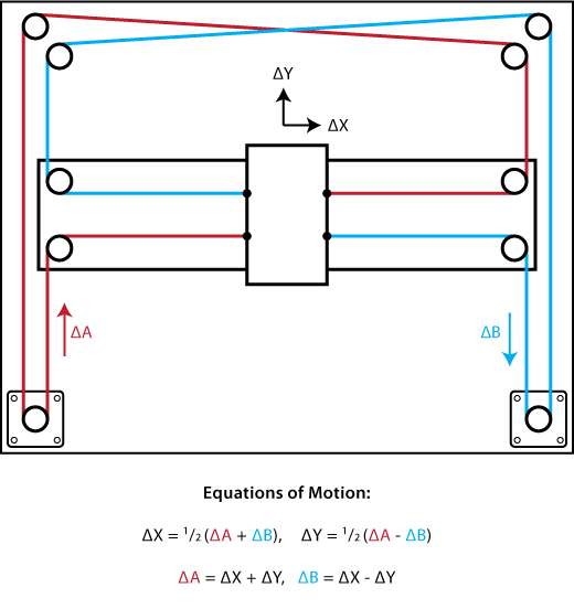
I've decided to go with a CoreXY design, which is pretty interesting in that it uses two belts to drive an X and Y axis, but by working together.
Now, I'm not the first one to build something like this, it's nothing new. However, i'm doing what I did before, and building it really big. This thing will hopefully have a 2' cubed printable area. I'm not 100% on that, but it's what I'm shooting for.

So far I've gotten the frame built up and some V-slot cut to handle the rails, but I'm going to start blogging about what I'm doing here and why, since there's so little information on CoreXY design out there.

Anyway, a quick picture on where I'm at right now:


Monday, January 23, 2012

Falcon Project

Sorry for the lack of updates here, folks. I've been very busy with a project which is big enough to have it's own blog, restoring my Mutoh Falcon Outdoor 48. I'll update this with interesting projects from time to time, but for now, my main focus is getting this thing working.

Check out all the posts and tons of photos over at http://falconoutdoor.blogspot.com

Wednesday, November 23, 2011

Battling tftpd

*Update!* If you are using this to actually host configs for IP phones that will be used on a live network, I strongly suggest using atftpd instead.
Atftp does not have these odd file permission issues that plain tftpd does (i.e. once a file is created (such as a log file from a phone) by tftpd, it cannot be overwritten for some crazy reason.) Most IP phones store their configurations on the server, and if they cannot write them down after the first time, users (and you!) will not be happy!


Alright so this new job has got me documenting everything the minute I do it, so that I know what the hell to do the next time something happens.

So, this time? It's something I'm doing for myself.

Installing at tftp server in Ubuntu.

I know it sounds stupid, but every tutorial is from 2005 and none of them work on the current version of Ubuntu nowadays. If you want a working tftp server, here's how you do it:

Install the tftpd program. This will also install xinetd, which is how it's started. inetd starts xinetd, who then starts tftpd. I know, dumb, but that's how it works.

$ sudo apt-get install tftpd

Next, we need to set up the file that xinetd will read when it starts tftpd.

$ sudo nano /etc/xinetd.d/tftp

Put this stuff inside it:

service tftp
{
socket_type = dgram
protocol = udp
wait = yes
user = (change this to your username)
server = /usr/sbin/in.tftpd
server_args = -s /tftpboot
per_source = 11
cps = 100 2
disable = no
}

Now, we need to make a directory that this thing will use to put/get files out of. It's commonly right in the root.

$ sudo mkdir /tftpboot

Make that directory readable/writable by your user

$ sudo chown youruser:youruser /tftpboot

$ sudo chmod -R 777 /tftpboot
(this step is required, so that new files created are able to be overwritten.)
Now things should be cooking. Let's try starting tftp.

$ sudo service xinetd restart
* Stopping internet superserver xinetd                                  [ OK ]
* Starting internet superserver xinetd                                   [ OK ] 

If things are NOT ok, then you need to check the logs. Xinetd dumps it's goodies in the syslog (/var/log/syslog). Tail that logfile (tail -f /var/log/syslog) in another console/terminal while you restart and you'll see what's going on.
In my case, I didn't have the user specified correctly, in which case xinetd just doesn't start tftpd.

Now, you should have tftpd running. Look for the open port on the machine, owned by xinetd. This process will be run by the system, so use lsof to check:

$ sudo lsof -i | grep tftp

You should get a line back like the following:
xinetd      942     root    5u  IPv4 5132137      0t0  UDP *:tftp

This means you're up and running! Try pointing something at your tftp server and see if you can get/put files. (Cisco switches, IP phones, etc)

If it fails, check the permissions of your chosen directory, and check syslog for errors. I've seen it noted that adding -v to the options in the tftp file (server_args = -v -s /tftpboot) will make it more verbose, but all I get with that is lines in syslog saying "invalid argument - ?"

Friday, August 26, 2011

Playing with Fritzing

So I've been looking at various chips to use for memory, and they all seem to be pretty much the same, so I decided to take one and start designing for it. I started playing around in Fritzing, making a simple schematic with just the micro and the SRAM to see how the software works.

Here's my schematic, autorouted by Fritzing. If I try and autoroute with that last R/W- CE line, it will crash the software. Maybe I can send that in...

This is just the 6802 Microprocessor and an Alliance Memory AS6C6264A 8Kx8Bit SRAM. Not all necessary lines are connected, the CS line goes through a decoder chip which isn't on here yet, and the power/grounds aren't wired up either.


This worked out pretty well, but I was really interested in trying out the PCB designer part, because I've tried a few before, and while they're interesting, they all have their quirks. Fritzing is no different, but there are a few little things that help. One in particular is the shift-click on bendpoints on traces.. It lines the trace bendpoint up in an intuitive way, though it does require a bit of getting used to in order to make things work the way you want. The autorouter leaves much to be desired, but it's still an alpha piece of software, so I decided to route by hand to see what I could do. Here's the result:


It's not too bad, yeah, I might not be able to fit a 16 mil trace between those pads, but I was getting a little impatient after things kept crashing and I wanted to get this blog post up. I just did a quick bit of hand-routing to make this work, which it seems to quite decently. Vias work, the way they should after you figure them out, and it's something I've been able to quickly pick up and run with.

One lesson I've come back to: Save often!

I'm going to keep going in Fritzing I think, laying out the schematic mainly and building parts I need, then I'll work on getting the traces all worked out on the schematic. I'm going to keep posting progress pictures, though this weekend will be a bit busy, going to see what I can get done.

Saturday, August 20, 2011

Starting out

Okay. So for this Type 'n Talk thing to work, I need to design a schematic. Then I can lay out a board, then get it made, populate it, etc..

Decided to give Fritzing a go. It's an interesting, relatively new electronics design software that's open-source and seems fairly friendly. I don't think it has an autorouter, but that's no problem, I can lay out the traces myself; there's not too many of them on this board. I'm combining  components too, so that should reduce part count and traces even further.

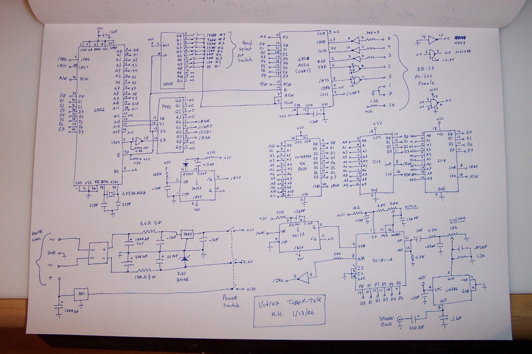
So, to give you an idea of what I need to do, I need to take this schematic, and create my own with new parts that I can actually get, and make it actually work.

The first thing I decided to tackle is the ICs. I don't know what a lot of these ICs are, I've never used them before. A lot of electronics veterans may know about them from seeing or using them in the past, but I'm new to this game. What's a 2114? a 6802? a 7442? Well, they used to be some industry standard parts. Every manufacturer made their own version of them, and they would prefix them with their specific letters to denote they made it.

This gets technical. I start explaining memory storage and how these chips work. If you don't want to know about that, you can skip.

If this gets a little 'teachy', it's because I just learned this stuff. It's really cool. This explanation may help someone else who would like to understand how this memory works.

Well, the chips I started out with are 2114's. They are 1024x4 bit memory modules. Here's the 1979 datasheet.
What does that mean? In these chips, memory is organized into groups. You'll usually see this type of notation such as 1024x4, 512Mx8, etc. This is basically how many 'cells' of how many bits the memory chip can hold.

Let's take the 1024x4 as an example. This means that there are 1,024 cells of 4 bits each. Imagine your house has 1,024 rooms in a grid, like an office. Each room has 4 light switches. You can go to any room, and turn on or off the switches, in any pattern you like. This is how memory is stored. Each 'switch' is a bit, and each 'room' is a cell. So, total, since each room has 4 switches, and there are 1,024 rooms, you can have a total of 4,096  switch positions, or 'bits' of information stored.

Now, how do you tell which room to go in?
The chip has row decoders, and column decoders. Basically,  they use binary to specify which row, and which column to enable, depending on how those pins are toggled, and what binary coded numbers are produced by toggling them.
For example, if we had row pins set to 1,0 and column pins set to 0,0 that would tell the chip to look in Row 2, and Column 0, and either read or write to that spot.
Reading and writing is easy, if you want to write, you set your row and column pins to the cell or 'room' you want to write to, then set the 4 inputs to the 1 or 0 bits you want to write, and toggle the write enable line to the write position, which will write the data into those bits or 'switches'. If you want to read it back, simply set the row and column pins as before, and then leave the write enable to read position. The contents of that cell will appear on the data lines.

Ok, back to our regularly scheduled program...

So, my dilemma is that the 2114's are no longer made. They haven't been made for years, and for good reason. Memory technology has come a long, long way since then and we have faster, bigger, lower power memory chips now. 2114's were about $10 apiece when they were originally made, and you can get ten times that much memory now for the same price. Luckily though, while the newer chips can store more things, they also work the same was as the old ones!

So let's look at a new SRAM chip from a common manufacturer, Cypress Semiconductor. It's model CY7C185.
This chip has 8Kx8, or 8192x8. Looking back at how we broke down the 1024x4, this means that this chip has 8192 cells (or 'words' as they are called in the industry) of 8-bits each. This means that the new Cypress chip can hold 65,536 bits of data. That's 16 times more data than the old 2114 chip, and they only cost about $2 per chip! The new one also reads almost three times faster than the old chip, and it uses about 4 times less power!

So the issue now is how to integrate this chip. Well, there's a reason I chose a x8 chip and not a x4 chip. See, the original circuit design combined two x4 chips into a single 'x8 chip'. Since all the row and column registers are tied together in the schematic, whatever row and column the microcontroller selects, is selected on both chips. Whenever the micro flips on the chip select, both chips are on. The Write Enable lines for both chips are also tied together, so the micro can't tell which chip it's writing to, so each time it writes, it writes in 8-bit blocks. If it only wrote 4 bits, both chips would still have their write lines turned on, so one chip would write garbage while the other one wrote good data! This means that they *have* to write all 8 bits at a time.

This makes it easy. It's already writing in 8-bit blocks, so just put in a chip that will handle 8 bits for each cell, instead of two chips with 4 bits each! For the row and column selectors, being that the new chip has more memory, it also has more pins for those selectors. However, since we're only going to be using the first 1024 cells (this is all the original memory chips could address, remember?), the cells above 1024 will simply go unused. No big loss, since the memory is so cheap. We will simply tie the other ends low so they are not used when selecting rows or columns.

Here's my diagram. The top drawing shows how the memory is organized now. Notice that the D0-D7 lines are split up evenly between the two chips. This is how they combine the two smaller chips into one big 'chip'.
The bottom diagram shows an example (using a different chip than I mentioned above) of how I could integrate a larger memory chip utilizing all 8 bits at once into something much larger.


So, that's about it so far. I'm starting work in Fritzing, going to have to add my own components in and such, and I'm still researching memory options. I'll post some WIP schematics soon!

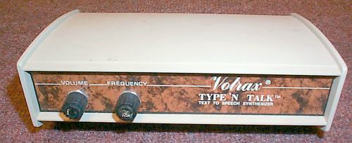
Votrax Type 'n Talk


Well, I have decided that I'm going to be building a Votrax Type 'n Talk from scratch. Well, aside from the Votrax SC-01 chip, that is.

I used to play with one of these a long time ago; my dad bought one and I would play with it at an old IBM computer, sending it text and making it say things. They're fun boxes, and they are (relatively) good at reproducing speech. They were made by a company called Votrax, which was a division of Federal Screw Works, in Detroit, MI. There's a lot more on their history on Wikipedia, so if you'd like to learn more about the company and the various products they produced, as well as how their voice synthesis works, check out that article.

The synthesizer is a basic design, uses a simple Motorola 6802 CPU with a 4K ROM and 8192 Bits of memory.
A really awesome guy has taken several Votrax products and de-potted the ROM/CPU, dumped out the ROM and completely traced out the schematic on the board. His website is here: http://www.kevtris.org/Projects/votraxtnt/index.html

Basically, my project is to take the schematic, and build a smaller, more modern version of the Type 'n Talk. Mine will have the same volume/frequency knobs, the same ROM, will operate the same way, with some improvements. Particularly, the updated version I'm building will have a USB port instead of a DB-25 serial, will do away with the baud rate switches (not necessary if I'm handling that internally) and will have a better power supply. Also, it'll have a smaller box, and more speaker outputs.
The difficult part is that the ROM has code in it that takes incoming ASCII text, interprets words into phoneme data, and feeds that into the SC-01 chip. The SC-01 is the actual Votrax chip that generates the speech from phonemes.


SO. I have the schematic, a list of parts, an SC-01, time, and the internet. LETS DO THIS.

Wednesday, May 18, 2011

Active Directory and BackupPC, continued...

Preface:
I originally wrote this post a long time ago. Looks like around 5/18/2011. While I never finished it, I came across it recently and think it deserves to at least be put out there to provide a bit of info that may help, rather than languishing in a draft. It may not end in a cliffhanger, but hopefully it will get you somewhere.


Well, in the continuing saga of BackupPC and Active Directory, the old BackupPC server that worked fine for so long finally died, prompting a new one.

Ok, so it didn't really die. The BackupPC box at my work has been a virtual machine (under VirtualBox in Win2k3 Server) that has had it's fair share of quirks. Yes, I'm not running VMWare or something high end, but it did the job, even though it needed to be restarted once a month or so. Mainly due to disk and network driver issues.

So, since we're getting a new server and the current one running the VM is being repurposed, I decided to pull an older P4 desktop out of the back to finally get a dedicated server running which should be MUCH more efficient and have less network/disk related issues. Obviously, this requires me to reinstall the whole mess.

I'm going to do it again this time, and do a better job of documenting it. I'll also be using the latest Ubuntu, Natty Narwhal, 32-bit Server edition, to do this. I'll walk through the steps of installing Linux, getting the machine on the domain using the newer Likewise-Open package, getting Apache up and happy with AD authentication, and then hook BackupPC into the whole mess. I'm going to have to do some interesting stuff with getting the pool over, though I may just say screw it and dump the pool since the data isn't that important. I will need to copy over the config file from the old BackupPC install though, so I don't have to spend another 5 hours configuring hostnames and excludes.

This post will be edited several times over the coming days, because it's going to take me a bit to properly do this.

Step 1: Installing Linux
The obvious first step here is to install Ubuntu on the machine. I'm using the normal Ubuntu Server 32-bit install disc from 11.04, Natty Narwhal.
The first (relevant) thing it's going to ask you is the hostname. I'm on a Big Corporate network, so as an IT Manager at a location, I only have access to do things to my location's OU. Unfortunately, when you join a computer to a domain without specifying where to put it, if there's no object, it tries to create it in the big "Computers" area, which I don't have access to. So what I do is create the computer object in my OU, and then make the hostname of the Linux box the same.
There IS a way to have Likewise-Open create in a specific OU, but I haven't played with that, and so I'm just explaining how I do it.
So, set the hostname to your created computer object's name. 

Next, you'll be asked what groups of packages to install. I choose OpenSSH (necessary to be able to SSH into the server) and Samba (for pulling data from desktops)

Step 2: Setting up Likewise-Open
The next thing to do after you get the machine up and running is to logon to it and get all the updates and such, make sure things are up to date. Then, install the Likewise-Open package.
$ sudo apt-get update
$ sudo apt-get upgrade
$ sudo apt-get install likewise-open
 The setup will ask you a question during the config of likewise-open regarding the Kerberos configuration: 
  • Default Kerberos version 5 realm This is (as the dialog explains) what the system will default to if someone tries to do a domain login as "person" rather than "domain\person". Basically, the default logon domain. This should probably be the same FQDN as the domain you're joining to.
 On my install, towards the end it says "Importing Registry Configuration", which sits there for awhile. I hit enter a couple times after a few minutes and it seems to complete; I'm not sure why it waits until enter is hit. Might be a little bug in the install script.


The Likewise-Open install guide has a few things that you need to do to prep the system for joining to the domain. I'm going to only run through a couple, but if you have issues definitely check that as it has more info on DNS and some other important things which may be already configured in Ubuntu, as the install guide is aimed at people loading the file directly onto a bare Linux system.
  • Check /etc/nsswitch.conf and make sure that the line hosts: is followed by 'files dns'. In Ubuntu 11.04, this is the default, so just double-check.
  • Make sure that /etc/resolv.conf contains nameservers that can perform SRV lookups for the domain you're trying to join. DHCP at my company already has internal nameservers in it, and provides the proper domains, so I don't have to do anything here. If you're using static IP and such, make sure that your nameserver can do SRV lookups.
  • Make sure you have your network set up correctly, i.e. primary gateway, firewall on the machine (if any), DNS lookups resolve properly to your machine name, etc. There is a laundry list of things to check on the Likewise-Open guide, definitely give it a once over before you start trying to join in case there's anything glaringly wrong. 
  • Next, we need to check the /etc/krb5.conf file to make sure it has the right domain info in it. You should see your domain listed as the default realm at the top of the file.
Step 3: Joining to the domain
This is the easy part. From the command prompt, enter the following:
 $ sudo domainjoin-cli join sub.domain.com DomainAdmin
where 'sub.domain.com' is your domain, and 'DomainAdmin' is a user that has administrative rights to join a computer.
If it works out, it should take a little while after entering the password to complete the join and do all the good configuration type stuff necessary to allow the machine to authenticate users via AD.

If successful, after it's finished you'll see a message telling you to reboot the machine or restart all services. I'm going to reboot, cause this isn't a high availability server or anything.

After the reboot, you can test the connection by attempting to logon with a domain user and password at the linux logon prompt. You should see "Created user: UserName" and it should log you on. It will even tell you if your password is about to expire!

As you can see, I've had a much easier time joining to the domain than I did previously, though most of that might just be from me not doing things correctly the first time around.

Next, we'll look at installing BackupPC and getting it working on the domain!

BackupPC: Getting that thang installed
Okay. Ubuntu server has version 3.2.0 of BackupPC, and while it's not the latest (3.2.1) there's not too much of a difference. I'm just going to use the one that comes with it for now.

$ sudo apt-get install backuppc
This will get backuppc installed. It installs x11 and a bunch of unnecessary stuff, but you just hafta kinda live with it for now. I haven't found a way to install it via APT without it.

Make sure you have Apache installed properly, it should have installed as a requisite of BackupPC. 

Now there's a couple ways to authenticate users via AD. One is via the LDAP module, which is nifty, but you need to have a user account and password that the server can use to lookup users in the domain. I don't like that, so I'm going to use Kerberos.
An interesting side-effect of Likewise-Open is that it seems to generate the keytab file for you! This makes config much easier, as we don't need to bother with a lot of stuff. You can check for the existance of it, it should be in /etc/krb5.keytab. You can also check the contents with this command:
$ sudo klist -k /etc/krb5.keytab
This will show you a list of all the bits inside it, you should see several lines listing your computer's name as well as the domain you've joined.
Now we need to make it so that Apache can read the file, as it's modules will need to see it to authenticate to the network.
$ sudo chmod 740 /etc/krb5.keytab
$ sudo chgrp www-data /etc/krb5.keytab
Now I'm not condoning this as the most secure way to do things, but I'm in somewhat of a low-security environment because I'm behind copious firewalls and such. You might want to come up with a better way to secure the keytab.

(I copied the following section from my previous post)

Now we need to edit the backuppc Apache configuration to tell Apache how to authenticate users.
The file to edit is located in /etc/apache2/conf.d/backuppc.conf
This is how my file has been setup. I have commented out the four lines at the bottom there, leaving the require valid-user line in place. I added the six lines at the top.
 
AuthType Kerberos
AuthName "Kerberos Login"
KrbAuthRealms CONTOSO.TEST.COM
Krb5Keytab /etc/krb5.keytab
KrbMethodNegotiate On
KrbMethodK5Passwd On

# AuthGroupFile /etc/backuppc/htgroup
# AuthUserFile /etc/backuppc/htpasswd
# AuthType basic
# AuthName "BackupPC admin"
require valid-user
 

Tuesday, March 15, 2011

Beds..

Well while things are going decently on the bot, aside from having trouble getting the PLA to stick to the kapton (it doesn't seem to like it like ABS does), I'm having a bit of trouble with bed temperatures.

The temps on the bed have a large gradient from the center to the outside of the bed. The thermocouple that I have kapton taped an inch or so from the edge reads 65C while the center of the bed reads 100C. I've checked independently with a IR temperature gun, and it's showing me the same thing. The edges are staying way cooler than the center. This has caused some issues where the far side of a print will start to curl a little and the center will stay (while doing ABS at least). This issue is somewhat  understandable as the aluminum is very thin and because of that, acts like a heatsink in the open air; the edges dump their heat quickly while the center is trying hard to keep things warm. I need something with a better heat transferrance and capacity.

I had previously purchased a larger heater mat cause I intended to buy one of the Mendel-Parts.com beds, since they're made from almost 5mm thick aluminum. That'd have some serious heat transfer abilities.
Unfortunately, it's kind of pricy to get that shipped from europe here, especially with such a commodity material as metal. So I started looking around for places to get the bed from, as it's simply a 9"x9" sheet with some holes drilled in it. The little notch is optional for me as it isn't there for clearance, just as a hole for the extruder to dump test extrusions into.

However, I got to thinking. If aluminum is good, then copper must be better! It has almost twice the thermal conductivity of aluminum (Copper: ~ 385 W/m K, Aluminum: ~ 204.3 W/m K) and I can get it relatively easily (though not cheaply). I went to OnlineMetals.com and purchased a 9" x 9" x 0.125" sheet of copper. It's nice because they will cut the sheet to your specs for you, and it can make things cheaper as well! It was about $70, so to bump things up to the $100 mark (where you get a discount) I added a couple pieces that my friend would need for his RepRap on there, as well as a version of the bed in 5mm thick aluminum, just in case the copper didn't work out.

The items came in today, and wow! The copper really is heavy. I hope that the steppers can drive this thing around. The Aluminum bed is also quite large.

I can't wait to get the new heater glued in so I can see how well the copper plate reacts to the temps, and if the temp gradient is the same.

Tuesday, March 1, 2011

Finally!

Well, after much time not working on this thing, I have the time and drive to do it. So, got down to business.

The RepRap, when we last left it, was in a mostly working state. Aside from the temp controller. After chasing down the odd issues revolving around problems with it not able to hold temp correctly, I really got serious about looking for issues. I finally found a problem in the power signal coming from the supply. It appears that the cheap Chinese power supply we ordered was indeed cheap, but also noisy. As you can see in the following video, the oscilloscope shows huge spikes and changing noise on the line as the thermocouple turns on and off. I should mention that this reading is on the thermocouple itself, not on the output of the power supply, even. It was creating huge amounts of noise.


I had a 0-15VDC 40A capable power supply (yeah, big) hanging around, so I decided to give that a shot. Hooked it up and the noise was gone, and the temp controller is much more stable now. It still fluctuates a couple degrees between when the heater is on or off, but it's within the limits of the controller's abilities to hold it mostly stable, so I decided to just go ahead and proceed with getting it up and running.

To start, I got a copy of RepSnapper and compiled it, and gave it a test STL and after much playing around trying to get the machine actually talking, I finally got things moving, and made a test print. It's not much to look at, but it's a print.


After this, I began working on Skeinforge to get it to make a decent gcode file. I had issues getting the plastic to stick to the cold kapton and aluminum, so since I already had a heater mounted to the aluminum, I set up my other temp controller and an SSR to control the 110v going to the bed heater. It heats up in about 20 seconds. Things started sticking MUCH better after that.

Following getting things to stick, I tried a few calibration squares, then a ring from Thingiverse to see how good it was working. The calibration cubes are coming out mostly squared up nicely, though I'm having some issues with flow rate. I think I'm not putting enough pressure on the filament in the extruder and I'm having issues here and there with it stripping out occasionally, usually due to the FTDI cable not being hooked up when the stepper controllers are powered on. If the enable line floats and so does the input, the steppers will drive all crazy until they're pulled in a certain direction by the motherboard. Here's a video of building one of the rings:


Last night I tried printing a few more rings as well as an object someone in the lab had tried to make (a mixing paddle from a bread machine) and it did a decent job, albeit with flow problems again. I printed a pair of tweezers as well. So far, so good. A few pieces of the machine aren't tightened up properly and they're falling off, but I'm keeping it together. I'm going to build  my own small control board and mount for the Omron controllers, and finish getting the wiring cleaned up. I'm looking at making one of the new sexy Wade's derivatives that popped up on Thingiverse recently:
 
It's got better accessibility to the hobbing as well as a better gear ratio and smaller styling. I'm excited to start printing stuff on this thing! Hopefully the blog will be going a bit faster now that we've got some activity!

Wednesday, July 14, 2010

Active Directory and BackupPC

This post is going to be slightly off-topic. Mainly because it's the best place for me to put this information.

When I spend a couple days getting a particular setup to work properly, I feel I should post about it as many others have to help someone out who's in the same boat. So, without further ado, here's how I set up BackupPC to work on my corporate network using ADS authentication.

For this setup, I'm using Ubuntu Lucid Lynx 10.04 Server 64-bit with the latest packages as of 7-14-10. This includes BackupPC v3.1.0.

My setup is this: I have the Ubuntu box (backuppc-srv) running as a VM on a local server. For all intents and purposes, this should not change any configuration as it's bridged networking. We have a set of Windows XP machines that need to be backed up. All machines including the server are joined to the corporate domain (Contoso) and have a FQDN of (contoso.test.com) I have a domain account that has the ability to create computer objects and join machines to the domain, however, I do not have console access to the domain controller. This will come into play later when we create the keytab.

The Ubuntu help sites have started recommending using Likewise to join the domain. While this is easy to do with a desktop, while trying to get Kerberos working, I had nothing but problems with it, and eventually removed it and decided to go about it with straight Samba. It's actually not that hard, and just requires a little work.

We first need to set up the machine to join the domain. I used this excellent blog post here which I will use several commands from to illustrate the process.

As the linked article mentions, it is very important to have a good working DNS setup on the domain. ADS relies heavily on it for authentication and will not work without being able to do forward and reverse lookups. Also, make sure that your machine has good time synchronization. Chances are, if you have a Primary Domain Controller (PDC) it will also be running as a time server. You should be able to use ntpd or ntpdate to synchronize time, which is also very important to Kerberos, as it is normally configured with a narrow clock skew. More than a few seconds difference and you can experience some issues.

To start, this command can be used to install the requisite packages to run Kerberos and Apache authentication:

backuppc-srv:~$sudo apt-get install apache2-mpm-prefork libapache2-mod-auth-kerb krb5-config krb5-clients krb5-user samba-client openntpd

Now that we have the packages installed, we need to setup Kerberos to authenticate to the proper domain.

Edit the /etc/krb5.conf file with your favorite text editor and start looking around. By default there are a few comments that may or may not be helpful. Here's how mine is:

[libdefaults]

# The following krb5.conf variables are only for MIT Kerberos.
        krb4_config = /etc/krb.conf
        krb4_realms = /etc/krb.realms
        kdc_timesync = 1
        ccache_type = 4
        forwardable = true
        proxiable = true
        default_realm = CONTOSO.TEST.COM

Under the next heading you should set up your PDCs.

[realms]
    CONTOSO.TEST.COM = {
        kdc = pdc.contoso.test.com
        master_kdc = pdc.contoso.test.com
        admin_server = pdc.contoso.test.com
        default_domain = contoso.test.com
    }

Now that those are set up, put in the last couple bits here to make things work right:

[domain_realm]
.test.com = TEST.COM
.contoso.test.com = CONTOSO.TEST.COM

Now those are out of the way, we can test the Kerberos setup by using kinit. domainuser is the name of some user account who is in the domain and enabled, i.e., it works on other machines.

backuppc-srv$ kinit domainuser
Password for domainuser@CONTOSO.TEST.COM:

Once you've done this, you can check to see if it issued you a ticket by using klist.

backuppc-srv$ klist
Ticket Cache: FILE:/tmp/krb5cc_0
Default principal: domainuser@CONTOSO.TEST.COM

Valid starting      Expires            Service Principal
07/14/10 12:00:15   07/14/10 00:00:25  krbtgt/CONTOSO.TEST.COM@CONTOSO.TEST.COM

Now we see that the account has been issued a ticket. You can then release the ticket with kdestroy:

backuppc-srv$ kdestroy 

Now we can setup Samba. Edit the file /etc/samba/smb.conf. These lines will be scattered throughout the file, if they're not there, just put them in the general section.

netbios name = backuppc-srv
realm = CONTOSO.TEST.COM
security = ADS
encrypt passwords = yes
password server = pdc.contoso.test.com
workgroup = CONTOSO

You should also add the keytab settings for completeness:

keytab method = dedicated keytab
dedicated keytab file = /etc/krb5.keytab

Now we can join the computer to the domain. Domainadmin is a user on the domain who has privileges to join a computer to the domain.

backuppc-srv$ sudo net ads join -U domainadmin

It will do several things which will eventually end up joining the computer to the domain.


Now you should ensure your /etc/hosts file is setup correctly. It will have your computer name (backuppc-srv) linked to your localhost as such:

127.0.0.1 localhost
127.0.0.1 backuppc-srv.contoso.test.com backuppc-srv

You need to add another line to this with your server's IP address. 192.168.1.123 is the IP address of backuppc-srv

192.168.1.123 backuppc-srv.contoso.test.com backuppc-srv

When this is all completed, we can now get a keytab so that Apache can use it to authenticate against the server. As the linked article mentions, a lot of the tutorials on the web mention using ktpass on the windows machine, but you don't always have access to that, or a secure method of transporting the resultant keytab into the linux box. Luckily you can just get Samba to get one right off the PDC.

backuppc-srv$ sudo net ads keytab add HTTP -U domainadmin

This will get a keytab, and put it into the default file specified in the krb5.conf file, which is /etc/krb5.keytab in this example.

You can now verify that the keytab was successfully retrieved by using klist.

ktutil: (the last command is a lowercase L)
backuppc-srv$ sudo ktutil
ktutil: rkt /etc/krb5.keytab
ktutil: l


This method is much easier than typing all that stuff and was just recently brought to my attention:
 
backuppc-srv$ sudo klist -k /etc/krb5.keytab

slot KVNO Principal
---- ---- ---------------------------------------------------------------------
   1   13 HTTP/backuppc-srv.contoso.test.com@CONTOSO.TEST.COM
   2   13 HTTP/backuppc-srv.contoso.test.com@CONTOSO.TEST.COM
   3   13 HTTP/backuppc-srv.contoso.test.com@CONTOSO.TEST.COM
   4   13            HTTP/BACKUPPC-SRV@CONTOSO.TEST.COM
   5   13            HTTP/BACKUPPC-SRV@CONTOSO.TEST.COM
   6   13            HTTP/BACKUPPC-SRV@CONTOSO.TEST.COM

This shows that there are the proper entries in the keytab.

You need to then give permission to Apache to read the file.

backuppc-srv$ sudo chmod 740 /etc/krb5.keytab
backuppc-srv$ sudo chgrp www-data /etc/krb5.keytab

Now it's time to get apache working. You can use the command a2enmod auth_kerb to ensure that mod_auth_kerb has been properly enabled.

Now we need to edit the backuppc Apache configuration to tell Apache how to authenticate users.
The file to edit is located in /etc/apache2/conf.d/backuppc.conf
This is how my file has been setup. I have commented out the four lines at the bottom there, leaving the require valid-user line in place. I added the six lines at the top.
 
AuthType Kerberos
AuthName "Kerberos Login"
KrbAuthRealms CONTOSO.TEST.COM
Krb5Keytab /etc/krb5.keytab
KrbMethodNegotiate On
KrbMethodK5Passwd On

# AuthGroupFile /etc/backuppc/htgroup
# AuthUserFile /etc/backuppc/htpasswd
# AuthType basic
# AuthName "BackupPC admin"
require valid-user


Now that apache is setup, make sure you restart it (sudo /etc/init.d/apache2 restart), or perhaps better, reboot at this point, just to make sure the domain join is working properly. After it restarts, try to access the backuppc web interface. If you are getting the Kerberos login prompt, login with your domainuser name. No domain prefix is required as it's set to logon to a specific domain and Kerberos on linux cannot handle cross-domain logons.

If you are having errors, it's best to tail -f /var/log/apache2/error.log and set the debug level to debug in the /etc/apache2/apache2.conf file to display errors while attempting to login.

If you get a failed to verify krb5 credentials: Server not found in Kerberos database error, that's usually due to DNS issues, double-check your hosts file that you have the right IP addresses and names listed.

Client not found in Kerberos database means just that, it can't find that username. Make sure it's valid on the domain. I found that trying to logon to backuppc using a local linux user doesn't seem to work afterward, maybe I'm not setting something up right.

Wrong principal in request usually has to do with the keytab file. Check to make sure it has the HTTP sections, and if it does, just delete and recreate it with the command above used to initially make the file. Remember to change the permissions back! This has been the fix for the authentication randomly dropping occasionally, for me.

Once you've got yourself logging on via Kerberos, edit the backuppc /etc/backuppc/config.pl file with the proper user settings. I found that i needed to add the domain to make it recognize the user.. i.e. assign a computer with 'user' set to domainuser@CONTOSO.TEST.COM and that should work when they authenticate. You can also add a user into the CGI admin group in the same file, in the same way to allow that user to have admin access.

You will need to make a modification to the samba command that BackupPC uses if you back up with a local user account that's on the computer and not on the domain. On the Xfer tab of the BackupPC config, just before the -U $user, add -W $host. This will tell Samba that the username you're specifying is for the 'local host' domain, i.e., don't try to authenticate to the active directory, only authenticate locally to the computer. In my case, the local backup user accounts are not valid domain users, so this change needs to be made.

I'll update this when I figure out how to get Single Sign-On working on this through IE6. Right now i'm getting a gss_accept_sec_context() failed: An unsupported mechanism was requested (Unknown error).

Tuesday, June 15, 2010

Stepper Driver is live!

I brought the completed boards that my friend had drilled and cut out to work, and started the process of populating the board with all the fun components that make it work.

I formulated a strategy, which was to install all the tiny vias, then use the large Chipmaster hot-air machine to flow the large chip and the big current sense resistors on, then solder on all the other smaller SMT components with a hot air pencil, then do the large through-hole components. I chose this mainly because if I were to hot air the large chip last, the air temp would cause many of the plastic pieces on the big components to melt, or blow some of the smaller components off the board.

First power up!
Overall, the technique worked well. I produced a working board with only one small short, which I located and fixed. I then took the board up to FamiLAB, where we tried to hook it up and get it working. The blue light came on, which is power, so we were quite happy there. Then, after fiddling around and finding we had a bad cable, we got it to start stepping!

We got RepRap host up and running and started jogging the stepper around on it, which worked great! We enabled and disabled microstepping, which seemed to also work quite well. All the LEDs and such were running properly, and the chip barely got warm. All good signs. We even took a short video of the first movement here:


Now tomorrow I need to start work on the second one, and I'll have enough drivers to run all the motors. Then it's on to finishing up the electronics...

Wednesday, June 9, 2010

We have PCB!

So up at FamiLAB last night, we spent some time getting the PCB setup going.. I got some containers to do the PCB etching and developing in, and a few other bits and pieces needed. I started the PCB thing by printing the masks onto paper and holding them to our fluorescent light source to line things up and see how well they would fit.
Fluorescent lights upside-down with glass for registration
Once I had the designs set up properly and it looked good, I printed them out on the transparencies we got. Then we lined them up, used a little spray adhesive on the far corners to hold registration, and opened the board.

The boards are a dark greenish color when you remove the protective sheet from them, the light blue is just a thick film that covers the board that needs to be removed. We pulled it off and set the board in the area we had decided on, and slid it between the glass and under the light. We then set the timer for 8 minutes and exposed each side for that amount of time.
Immediately after developing. Green is the resist.

After exposing, you can barely see the pattern on the board. The dark green has changed to a dark yellow-green, so it's hard to really tell without a bright light, which you can't use yet. Next, you drop the board into a mix of 1 part developer to 10 parts water, and swish it around. Immediately the developer begins to remove the resist and you can see the circuit pattern.


After developing, we needed to actually etch the PCB. We mixed two parts Hydrogen Peroxide with one part Muratic Acid and used that to etch. This stuff fumes pretty good when you mix it, so I'd advise doing that bit outside or in a well-ventilated area. Careful breathing around it or you'll be coughing a lot. We dipped the PCB into the solution and began swishing back and forth by tipping the container. The solution begins to turn green quickly and you can see wisps of material coming off the board, but the process takes about 4 minutes before you see any clear progress. This usually starts around the edges where the copper begins to be completely etched away, revealing the fiberglass board beneath. The total time we had was about 6-7 minutes of gentle agitation and flipping the board every so often.
Final product. Green is stains from removing the resist.


After etching has completed, we rinsed and dried the board, then removed the resist with Acetone. It comes off pretty readily, but also seems to stain the fiberglass. Not a big issue. What's left is ready for drilling and soldering. I used a script in the EAGLE software called 'drill-aid', which takes the large holes normally printed for the vias and components and fills them in, leaving only a tiny 0.3mm hole in the center. This helps with drill centering, I'm told, so I went ahead and used it, and the tiny holes etched perfectly.

The finished product is really good. Although I still would like to get it on the stereoscope at work and take a look at it really up close, everything I can see went perfect. The process was so complete, that even a place where the toner had a few holes showed exactly the same on the board. (The toner is several years old, as is the printer, an HP LJ 2200D.) We're really excited about the possibilities of what we can make with just some simple work on the computer. I'm really interested to try my hand at laying out some boards myself!

Those who have been working with the Stepper Driver 3.2 will notice that the board there is a little messed up. I accidentally mirrored both sides, and this caused the board to be etched incorrectly. Now there's no way to actually make these boards work, so we're calling this our photoresist test board, and we're going to do another using better transparencies, a better printer with darker toner and higher resolution, more accurate registration marks, etc. Hopefully the next will turn out just as good, or hopefully even better than the first!

(There will be a video of the etching process posted tonight, I need to edit it up a little.)

Tuesday, June 8, 2010

Almost there...

Well, we're still working on finishing up the bits and pieces of the Mendel. Mainly, we need to get the PCBs done for the stepper controllers. My partner in crime ordered some stepper motors and those should be coming in today or tomorrow, and we'll be using those with the stepper controllers to get this thing running.

In my previous post I was talking about the Stepper Driver 3.0 that we were going to be building. Well, I got a short email dialogue with Zach Hoeken and he informed me that the modifications that Nophead suggested were made on the newer revision of the board, which he directed me to. (the XLS file is out of date, schematics are up to date)
So, the only problem is that I ordered all 1206 parts, when the new revision changes up a lot of components for 0805 parts (SMT part sizes). This causes an issue cause the parts I ordered are too large now to fit on the revised board's pads. So, I need to order all new parts, which I did yesterday. Hopefully the LEDs will be nice.. I got a good variety.. Deep Red, True Green, and Hyper Blue. RGB are my favorite colors to have on things.

We got the PCB boards and developer in, and we're going to make some Cupric Chloride to etch the boards. It's much safer than the Ferric Chloride, and better for the environment too. I spent last night working a little in Eagle. The light version won't let you panelize the board because it's too big, so I exported each side of the board as a PDF and then imported it into Inkscape. From there, I created an outline the same size as our board to help me in positioning the sides, then used align tools to create top/bottom layers. Now I can mirror the top layer and print them onto transparencies. We're building a UV light source with a lot of LEDs to see if that will expose better than fluorescent lights. It seems to be pretty sensitive, the package says to expose for 60-90 seconds under "exposure unit" which we're assuming is a UV source. or 6-10 minutes under a normal fluorescent lamp.

I got around to redoing the H bridges on the extruder controller, because I had hooked it up backwards to 12v at one point and blew the H bridges. So now I have a new set of H bridges on the board, so we should be good to go. However, I'm still going to be using the Stepper Driver 3.2 on the board. I may use the 3.2 boards I'm making for the X and Y axises, and the normal ones for the Z and extruder, as they require less precision. The 3.2 boards are tunable via 4 potentiometers and also have selectable microstepping. That will be an interesting feature to experiment with.

I'll try to get some photos or video of the etching process, as I think it would be a cool thing to watch!

Tuesday, June 1, 2010

Lots of progress!

Well, I apologize for the lack of updates, but we're in a pausing point here, so I will post a bunch of stuff that documents our progress since the last post.

When we last left our hero, he was having issues getting the MakerBot to work properly with the new FiveD firmware. Since then, we've managed to figure out what's up, remove those offending M codes from the file (M101, M103) and get printing again.

I've gotten the Wade's extruder all tuned up in Skeinforge, and it's doing an awesome job printing parts. We've even gone back and reprinted parts during our assembly that were done on the old Plastruder, and they've come out with much better tolerances on the new extruder. I've gone ahead and printed out another copy of it to use on the Mendel, so we will see how it works on there!

The Mendel. Yes, we started construction as we neared just a few parts left, and have gotten it pretty much completely built! There are a few little quirks here and there, like if you're using Josh Updyke's milled plastic frame vertexes, you should add another 1/2 to 3/4" to your x-plane rods. We added more washers to the Z belt bearings to space them out further from the plastic. We created our own M3 set screws with a Dremel, and hopefully have a good hobbed bolt for using on the new extruder!
I've almost finished up the HeatCore for the Mendel, which we'll be using temporarily while I experiment with the cartridge heater and copper block I'm building.

(When I say "we" I mean myself and another friend at our hackerspace, who is also building a Mendel.)

While I originally planned on documenting the entire build by photo, we had forgotten to do this and decided that when we build the second one, we will try our best to document the build process.

Other than that, the build went fairly smoothly. Belts are attached, frame is squared and tightened down, and we got some of the electronics mounted up on it. That's our current holdup. I used one of the stepper drivers in the MakerBot to drive the stepper for the extruder, and the TechZone kit only comes with three. So currently we're at two stepper drivers, and one half-broken extruder controller (I hooked the 12v up backwards and fried the H bridges.. but hopefully we won't need those).
To fix this dilemma, my friend an I have decided to build our own stepper driver PCBs. TechZone will sell individual PCBs, but we decided that it would be interesting to try the new 3.0 driver and see how well it works. We have PCB making supplies, and are currently in the process of getting a couple more things. We're going to go ahead and try the UV method to put down the resist, so hopefully that will work out well.

I've asked around about people using the 3.0 drivers, but all I can find is a forum post saying they'll be available for purchase sometime around February.. Well, it's been quite awhile since then, and the design on the SourceForge hasn't changed in 5 months or so. I'm assuming there just hasn't been any more testing on it. We've got the components ordered up to build 3 of them, and the tools to do all the SMT work. Hopefully we'll be able to get a usable board out of this process. We will also document what we're doing here, cause it's a pretty exciting thing to make your own PCBs and build them!

Aside from that, the axises on the machine are all moving with the stepper controllers we have. The TechZone board did not come with a bootloader burned on the chip, but luckily we had a USBtinyISP that we used to burn one on there. After that and a quick load of the FiveD firmware, things are moving around. We'll do the same for the extruder controller soon and hopefully it'll be running the machine within a week or two! Then we can start tuning Skeinforge again. I can't wait.

(photos will be posted later today)

Saturday, May 1, 2010

FiveD MakerBot Mishaps

Well, not to start out unhappy, but I've been working a lot on trying to get this thing to work right. It's not easy, let me tell you. I've had a few successes, but it seems I've run into every problem possible while doing this.

Now I've got my machine set up with the endstops and motor directions (by moving endstops and reversing motor cables) so that from the front, it plots in the same direction as all the software we use shows us things. i.e., origin is closest to viewer, left. (Bottom-left). This helps not build parts backwards, and makes visualizing the platform and x/y movements a bit easier.

The geared extruder is hooked up and running well. Haven't had many issues so far with the extruder itself; as a matter of fact it's gone quite well. The big part has been getting the table and software to work well.

A lot of the issues I had tonight dealt with Skeinforge. I'm using the latest version as of the time of this writing (2010-04-26). The RepRap host software (once I figured out some decent settings, which I'll post tomorrow) works good enough to get out a demo print. It's not perfect, but it will build an object.. roughly.

The objective here is to use Skeinforge's Gcode creation to build objects, since it's much more developed than the other. We still use RepRap Host software to send the gcode to the printer, but Skeinforge is doing the creation. I'd like to try/use RepSnapper soon, but it has issues with the 3d on this laptop.. seems the Intel drivers on here aren't really up to par for 3d stuff. We'll have to wait until they fix that. It doesn't run all that hot in the VM on here.

Had an issue earlier with the Z axis not working correctly. Turns out, Skeinforge's Z feedrate needs to be set quite low.. mine's set to 1.5mm/sec. Set anywhere higher and it freaks out a lot..

My main problem was that I had issues with it doing odd things.. I tried printing calibration blocks, but they definitely were not correct, and when I tried printing a 20mm solid block, I knew we had an issue.. Here are the photos:

Three calibration blocks. That triangle is there instead of the second shell on the other two sides..

20mm solid calibration block. This one's outline was extruded as huge blobs in the corners for some reason.
With these two, they have very different and odd issues. Mainly, the extrusions are not working properly. Visualizing the Gcode in RepSnapper shows that the code is proper.. somewhere between the code and the machine, something's not getting interpreted correctly.

So I did some investigating.. I loaded up the same object in Skeinforge and RepRap Host, and generated gcode files, and tested printing them. The RepRap Host file printed properly, and the Skeinforge file didn't. I then opened up the Gcode files side by side and tried looking for differences between the two.

In the Skeinforge file, whenever the extruder starts and stops, the file issues M101 and M103 codes. These are extruder start/stop commands, usually used with DC gearmotors. They tell the controller "start extruding, stop extruding" all at the preset speed. However, with stepper motor extruder drives, the extruder is treated as another axis, and therefore does not need on/off commands, as the stepper routines and controller take care of positioning the stepper appropriately.

One would think that these commands would be ignored, then. However, the RepRap Host file did not contain these codes. When I removed them from the Skeinforge file and reprinted (using the RepRap Host software), the file printed properly. I don't know what is causing this, the firmware or the host software, but one of the two just can't seem to handle those codes when it's using a stepper extruder. I used a simple find/replace command to delete them, and the files Skeinforge produces are working now.

Wednesday, April 28, 2010

Success!

Finally some good news!

Was up at FamiLAB last night working on the MakerBot. Got pretty much everything working right, defined some temperature sensor stuff and configured the extruder controller's firmware and uploaded it.
Did some simple tests with temperature and the HeatCore, found it's working well! The temps with the thermocouple are rock solid, and the PID on the extruder does a great job. I decided to run some test extrusions just to squirt out some filament, and they're great! Coming out nice and smoothly, if a bit slow. Temps seem good, it's not burning the filament, and I went through a few start and stop, heat/cool cycles to make sure we weren't having any issues with the nozzle. Everything looks good so far!

I decided to push my luck really hard and get it to try a simple build, but the X axis just kept driving itself into the wall, and the RepRap host software seems to be buggy at best when it comes to working with Gcode files.. I need to play around with it more and figure out what it's trying to do.

I've taken the stock MakerBot electronics and used them as-is, no mods to the boards or anything. All I've done is take an extra Stepper Motor Controller from my Mendel electronics kit and hook it's step/direction up to the I2C connector on the motherboard with a 3 pin header. All that's needed for the stepper controller to operate is step, direction, enable, and ground. Enable is tied to ground so that the board is always on. Step/Dir will depend on the connector you are using coming from the stepper controller, but I'll post a small diagram a bit later. This is hooked into the extruder's stepper motor, so the motherboard actually controls the extrusion steps instead of sending that info over RS485 as MakerBot does. The extruder controller is now only used to control temperatures of the nozzle, bed, and a fan if used.

The thermocouple is attached using a Thermocouple Sensor board from MakerBot. I'm using the AD595C for higher precision, and have the thermocouple taped so that the tip rests in the thread near the end of the nozzle, not touching the HeatCore. The sensor board has three wires; Vcc, GND, and Sig. I hooked these up using a small 3-position connector that came with my Mendel electronics kit, and plugged them into the MakerBot extruder controller on A7.
The FiveD firmware has support for Thermistors, AD595 Thermocouples, and MAX6675 Thermocouples. All that's needed to do is edit configuration.h to uncomment the proper thermocouple #define line, make sure the others (such as USE_THERMISTOR)  are commented, and change the #define TEMP_PIN to 7. This will set up the unit to read the AD595 from analog pin 7, and it will work just as normal. Need to be careful not to short the thermocouple wires as they're bare, and they will cause spurious readings if they're shorted. A single wrap of Kapton around the leads just behind the welded tip should be sufficient.

As far as further configuration of the FiveD software for MakerBot, I'm still trying to get it to a working fashion.. The axis can be easily calibrated using the standard method prescribed by RepRap. I used the 100mm to start though, so it would take less time to calibrate. All movements are accurate right now. I'm working on getting the home offsets correct, and hopefully being able to use the build limits as well so it doesn't try to build off the bed.

I will post more photos and perhaps a video tonight when I head back up to the lab to work more on this. Until then, here are a couple I took with my phone last night.


Monday, April 26, 2010

Finally getting somewhere..

Well as you may know from reading previous posts, the MakerBot at FamiLAB decided to puke up and break it's extruder somewhat. I tried to fix it, it kept having issues driving the DC gearmotor, and it was basically nonstop unhappiness. So, I decided, with all these Mendel parts hanging around, why not incorporate some of them into the MakerBot to get it at least up and running so it can print us a Mendel?

So here I begin...

Using the official MakerBot firmware with a geared stpper extruder is just way too much work and isn't really going to cut it. So, I decided to try and get RepRap's FiveD firmware up and running on the unit. It'll be good for a couple reasons.. One, I can do a few more things than I could with MakerBot, there's faster releases and better support for mods, since it was built to run a stepper extruder and has support for thermocouples out of the box. Two, I get more face time with it to really understand how that firmware and the apps work, so that when I finally get the Mendel built I'll already be pretty experienced in how to operate it and get things going.

So, I started off on that last night, getting the FiveD firmware set up with all the right pins, compiled, and uploaded to the MakerBot. I wired up a spare stepper motor controller to the extruder stepper and the I2C pins on the motherboard. I believe the H bridges in the extruder are kind of shot, so I'm doing this to get it running for now. I'm going to be making up a little mounting plate very shortly to get the Wade's geared extruder mounted up on the MakerBot Z platform. I may just clamp it to one side for now, just to test and get things moving, but I do want to get it set up properly with a bracket.

I calibrated all the axis and they seem to be moving proportionately now. Since the machine wasn't using endstops before, I had to set them up, test them and build some endstop triggers, which I made out of beer cans that happened to be laying around at FamiLAB. They seem to be working well, but I need a better way of attaching them as electrical tape just isn't cutting it. Other than that, auto-homing works properly now, all axis move, and are accurate.

The next step for hopefully tonight will be to get the extruder mounted up and start testing it.. I'm not so sure the speed settings are correct right now, but that's part of testing. I have the 0.5mm refsynderb nozzle in there and it's pretty much ready to go, just need to screw on the MakerGear HeatCore, attach my thermocouple and test that, and we should be ready to roll. I need to figure out how to get the heated build platform operational as well...

I'll be posting all this on the MakerBot wiki, as converting a MakerBot over to a geared extruder and FiveD has been an interesting task. I've been gathering some notes on the topic, and I'll be posting some pictures as well.

Thursday, April 22, 2010

Well I tried my hand at modifying some firmware and such, was a bit of a bust but here it goes:

Changed the v1.8 Heated Bed firmware to support the stepper extruder and also modified some code to use a thermocouple instead of a thermistor for the extruder temp sensing. Went up to FamiLAB and tried it out.. the thermocouple worked fine, but the stepper motor would not mobe. I'm not sure what the issue was.

The unfortunate thing is that there's no mention of how to wire up a Lin Engineering stepper to an extruder controller. They use Red/Blue/Green/Black wires, and I ohmed out the stepper looking for the two coils, which I found, and hooked up to the 1A/1B/2A/2B posts on the extruder controller. Tried to enable it and the H bridges got really hot, but no motor movement. The bridges stopped outputting power after that.

Looking in the Makerbot Operators group, someone mentioned that having a stepper connected that was less than 6 ohms might cause the H bridges to burn up; the Lin Engineering ones are about 1.8 ohm. However, they're also recommended on the RepRap website as steppers to use on the extruder controller. I'm a bit confused here, how are they normally used? There's a distinct lack of documentation as to what the resistance should be across the stepper terminals, so I'm of the assumption the H bridges were bad anyway and I didn't screw up there.

However, I did manage to screw up afterwards. Some folks in the Reprap channel on freenode were trying to help me troubleshoot the problem, when I managed to find out that the extruder controller has no reverse current protection in it. Hooked the 12v up backwards and blew the H bridges on my new board. Well damn.

So I'm ordering 6 new H bridges from Digi-Key, hopefully i can just replace them and that'll fix the boards, and perhaps try again to see if it was the bridges or if the stepper is the problem.

If anyone has some insight into this, it would be much appreciated. Been an ordeal just trying to get this working..

Monday, April 19, 2010

Slowly moving forward

Well, I haven't posted recently because I haven't spent much time actually building this thing, but here's a post to sum up what's been going on as of late. It's a bit long, but a lot is talked about here! MakerBots, Extruders, Thermocouples and firmware!

Friday, March 26, 2010

Electronics

Well, over the last couple days I've gotten a few pieces in.

- The geared extruder based on Wade's design
- Full electronics set for the machine
- Copper bar and cartridge heater for the barrel

So here's a few photos:

First, the extruder. This is how I assembled it, I believe this to be correct based on the illustrations I've seen

Extruder with nozzle